Other Parts Discussed in Thread: LAUNCHXL-CC2640R2
Tool/software:
Hi,
Currently using CC2640R2F Simple Central project. Where facing an memory corruption and sometime we seeing complete Page30 is filled with 0xFF data.
Test Case to reproduces the flash issues(mention Above):
1.After successful connection & Bond save we are transmitting data from central to peripheral in that time we are disconnecting the Power supply to the module(central Device) only the VCC not GND from supply.
#define AT_PARAM_ADDR  0x1E000
#define AT_PARAM_PAGE  30

void read_flash_parameter(void)
{
	HalFlashRead(AT_PARAM_PAGE, 0, (uint8_t*) &RamFlashData, sizeof(RamFlashData));
}

void write_flash_parameter(void)
{
	HalFlashErase(AT_PARAM_PAGE);
	HalFlashWrite(AT_PARAM_ADDR, (uint8_t*) &RamFlashData, sizeof(RamFlashData));
}
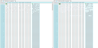
Here I have attached an image for both corrupted and non corrupted flash which on page no 30.

For your references we are attaching the central and peripheral binary files. And we are attaching the code how we are doing read and write operation to flash.
*Note*
1.We are not accessing the Flash upon sending the data or upon connection.
2.In the Application we are taking action based on the GPIO inputs.
3.UART not initialized on the central code.
Tool and SDK Details for Both:
SDK: simplelink_cc2640r2_sdk_4_40_00_10
CCS : CCS 9.1.0
Hardware Details Central Device:
GPIO Details:
GPIO 1 = DIO27(AS Input).
GPIO 2 = DIO26(AS Input)
GPIO 3 = DIO25(AS Input)
GPIO 4 = DIO24(AS Output)
Boot Pin:
GPIO = DIO7(High; Normal Operation)
Hardware Details Peripheral Device:
Boot Pin:
GPIO = DIO7(Low; Normal Operation)
UART PIN:
GPIO = DIO2(RX)
GPIO = DIO3(TX)
Based on our current analysis and findings, flash data is corrupted during the power on/off test. It is easily reproducible. We need to protect the flash content at any unintentional circumstances and immediate response is needed.
Thanks.

