This thread has been locked.

If you have a related question, please click the "Ask a related question" button in the top right corner. The newly created question will be automatically linked to this question.

CC2652R7: Setting the Application Reset Vector with a Custom Bootloader

Part Number: CC2652R7
Other Parts Discussed in Thread: SYSCONFIG

Tool/software:

I've got a project on a custom board using the CC2652R7 with SDK 6.30 and a custom Bootloader.  The Application project is based on the simplePeripheral TI-RTOS example, and the Bootloader is based on the no-RTOS nvsExternal example.  The Bootloader does its thing and then jumps to the Application using a call to jumpToPrgEntry(0x00000000);

void jumpToPrgEntry(uint32_t prgEntry)
{
    static uint32_t temp;
    temp = prgEntry;
    // Reset the stack pointer,
    temp +=4;
    asm(" LDR SP, [R0, #0x0] ");
    ((void (*)(void))(*((uint32_t*)temp)))();
}

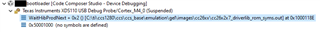
This works fine, and the Application code runs.  When we've downloaded a new version for the Bootloader to install, however, the Application calls SysCtrlSystemReset();  This is the part that does not work, and I'm certain it has something to do with how the reset vector is configured.  I have been trying to change the reset vector for the Application to point to the Bootloader, with various results, none of which is the one I want.  I have gotten it to simply restart the Application (skipping the bootloader), I've gotten it to hang in a FaultISR, and I've gotten it to hang in a WaitHibProdNext(), but never have I gotten it to go back to the bootloader on its own.  I will point out that I am aware of "halt in boot", and the hangs occur even off the debugger, even after a power cycle.  With the debugger, if I press the CPU Reset button in CCS, it goes to _c_int00() in the Application code, but if I click the Reset button, it goes to main() in the bootloader.

There appear to be like 6 different places to define all these things, and I can't find any documentation that actually specifies which one controls what.  I can attach the linker command file, but can someone explain to me what all these actually do?

  1. Linker command file:
    1. Application and Bootloader:
      1. /* Retain interrupt vector table variable */
        --retain=g_pfnVectors
  2. Linker command file:
    1.  Application:
      1. /* Override default entry point. */
        --entry_point ResetISR
    2. Bootloader:
      1. /* Override default entry point. */
        --entry_point resetISR
    3. Note those are different functions, with different capitalization, as defined elsewhere by TI in their respective example projects
  3. Linker command file:
    1. Application (FLASH_START = 0x00000000:
      1. SECTIONS
        {
        .intvecs : > FLASH_START
    2. Bootloader (BOOTLOAD_BASE = 0x000AA100):
      1. SECTIONS
        {
        .intvecs : > BOOTLOAD_BASE
  4. Linker command file:
    1. Application:
      1. -u_c_int00
        --retain "*(.resetVecs)"
        --retain "*(.vecs)"

        SECTIONS
        {
        .resetVecs: load > 0
        .vecs: load > 0x20000000, type = NOLOAD
        .ramVecs: > SRAM, type = NOLOAD, ALIGN(256)
        }

    2. Bootloader:
      1. Same except .resetVecs: load > BOOTLOAD_BASE
  5. Sysconfig GUI editor
    1. Device Configuration
      1. "Set Address of Flash Vector Table"
  6. Sysconfig text file
    1. Application only, from example project:
      1. Hwi.resetVectorAddress = system.utils.bigInt("00000090",16);

There are so many references to vectors, and they seem somewhat contradictory, and I didn't even know about that last one until I found the related question while trying to search here first.  What do all these do, and which ones do I actually want?

  • Hi Chris,

    What version of the SDK are you evaluating?  I'm using the off-chip BIM and off-chip Zigbee switch (or you can reference the BLE simple peripheral version) as a command linker file reference.  It's a good starting point since it has the same bootloader / application setup as your target.  Are you sure that the Bootloader is the only project which loads the CCFG?  For the BIM, the linker command file does not share the same inclusions as the application.

    -u_c_int00
    --retain "*(.resetVecs)"
    --retain "*(.vecs)"
    
    SECTIONS
    {
    .resetVecs: load > 0
    .vecs: load > 0x20000000, type = NOLOAD
    .ramVecs: > SRAM, type = NOLOAD, ALIGN(256)
    }

    It may be worth doing a diff compare to determine whether there are any noticeable differences.  You can also review the output map files for accidental section overlap.  The example application command linker file also has an entry group:

      GROUP > ENTRY
      {
        .resetVecs LOAD_START(prgEntryAddr)
        .intvecs
        EntrySection
      }

    Hope this helps,
    Ryan

  • I've got a project on a custom board using the CC2652R7 with SDK 6.30 and a custom Bootloader.  The Application project is based on the simplePeripheral TI-RTOS example

    SDK version is 6.30, as stated.  Application project started as the BLE simple peripheral, as stated, and its linker command file was more than just a reference; it's only slightly modified to include our bootloader memory regions.

    I will check out this off-chip BIM project, but in the meantime, can you explain what any of the above items I listed actually do?  Or at least tell me which one determines where the CPU jumps to after a CPU Reset?  Surely someone knows where the actual source of this is.

  • Sorry about missing the version and forgetting to include the TI Arm Clang Compiler Tools User’s Guide Linker Command Files description.  The boot entry is determined by the CCFG which is why it's important that this location is being written by your bootloader and not the application.

    Regards,
    Ryan

  • So, my vectors and everything are fine.  If I wait long enough and reboot the board enough different ways, everything works fine from that point on.  My bootloader works, the OTA works, application can reset to bootloader, bootloader can jump into application, back and forth as intended through multiple version updates all day long.

    But run it on the debugger once, and it keeps getting stuck on reset again until I can magically get it back out of that state.  I know I originally said "I will point out that I am aware of 'halt in boot', and the hangs occur even off the debugger, even after a power cycle."  But I take back the "aware" part, because my assumption there was that this wasn't Halt in Boot, because I thought a power cycle off the debugger would have cleared that.  Apparently I was wrong, because it's absolutely still halting in boot, disconnected from the debugger, after removing and replacing the batteries.

    How do I actually, definitively clear Halt in Boot?  This "wait a few hours and reset it 47 times" strategy can't continue.

  • Hi Chris,

    I've only ever known HIB to affect device software resets when previously connected to the JTAG debugger.  What you are describing (difficulty to run the application well after the JTAG has been disconnected) sounds like instability to correctly startup from custom hardware.  Do you have any details about your power supply rise time and XTAL crystal stability?  Is the system more stable when using a dedicated power supply instead of batteries?  Is the ROM bootloader enabled and can you confirm that the bootload enable pin is not active on startup?  I highly recommend that you submit your design to SIMPLELINK-2-4GHZ-DESIGN-REVIEWS for further review.

    Regards,
    Ryan

  • The board is a partner's existing design.  We are merely writing new code for it.

  • Thanks for the information.  I assume this board has no issue with basic application code that doesn't use the custom bootloader?  Please compare the differences in CCFG between functional and broken setups which may help determine any discrepancies.  

    Regards,
    Ryan

  • Only difference in CCFG when bootloader is present is the Flash Vector Table address specified in sysconfig.

    CCFG.setFlashVectorTable = true;
    CCFG.addressFlashVectorTable = 0x000A8100;

    When running application only, the bytes at 0xAFFEC are 00 00 00 00 for the normal 0x00000000 reset vector.

  • And on the application-only version, are there any reboot issues whether exiting a debugger session or free-running?  

    This "wait a few hours and reset it 47 times" strategy can't continue.

    This is not expected in any regard, HIB or otherwise, so I need to further understand the delta between functional and faulty setups.  For what it's worth, here is a Debugging from the BIM to the application section of an SLA which should be relevant for your custom bootloader as well.

    Regards,
    Ryan

  • I'm telling you, there is no difference in behavior between the application-only version and the version with the bootloader.  They both reset to their respective expected reset vectors except when getting caught by WaitHibProdNext in the exact same scenarios.  The delta between functional and faulty is completely independent of anything I do in either version of code image setup, and is 100% tied to the debugger state.

    If I run the application only, it runs on the debugger, starting at 0x0, and I can CPU Reset or Restart it in the IDE back to 0x0 and run it again; everything works until it does a reset not initiated by the debugger.  Soft reset off the debugger, or power-on reset whether the debugger is still connected or not.  Then it doesn't run.  If I reconnect to the "running" target and pause the debugger, I see this:


    This happens regardless of whether I cycle power while still running through the launchpad debugger, disconnect the board from the launchpad JTAG while still running first before I power cycle, or stop the debug session before disconnecting the board from the launchpad JTAG and then power cycle.  I can then cycle power until I'm blue in the face, but the board will not run.  Reconnect, and I will be stuck at WaitHibProdNext every time.

    If I run the bootloader+application, it runs on the debugger, starting in the bootloader and jumping into the application, and I can CPU Reset it in the IDE back to application start or Restart it back to the bootloader and run it again; everything works until it does a reset not initiated by the debugger.  Soft reset off the debugger, or power-on reset whether the debugger is still connected or not.  Then it doesn't run.  If I reconnect to the "running" target and pause the debugger, I see this:

    This happens regardless of whether I cycle power while still running through the launchpad debugger, disconnect the board from the launchpad JTAG while still running first before I power cycle, or stop the debug session before disconnecting the board from the launchpad JTAG and then power cycle.  I can then cycle power until I'm blue in the face, but the board will not run.  Reconnect, and I will be stuck at WaitHibProdNext every time.

    I have found what seems to be a deterministic "solution."  It wasn't that I waited a few hours and reset it 47 times; wouldn't matter how long I waited or how many resets I would have done the way I was doing them.  What made it finally work the last time was the way I reset it, which I now realize was simply due to me disconnecting my laptop and returning with it after a meeting.  But I have managed to repeat it consistently:

    So, you know what does work?  Leaving the launchpad debugger connected to the target board over JTAG, but unplugging the launchpad USB cable from the PC that CCS is running on, and then plugging it back in.  Then my board is off to the races, I can unplug the JTAG, and every subsequent soft reset and power cycle works just fine.

    Can you explain this?

  • I would imagine it has something to do with the custom hardware JTAG line parasitics causing a faulty JTAG state that changes depending on the hardware configuration and which/when cables are modified.  That is why I recommended a hardware design review (especially if this behavior doesn't occur on a TI LaunchPad).

    Regards,
    Ryan

  • It may also be worth investigating whether modifying the targetConfigs/CC2652R7.ccxml file's Target Configuration -> XDS110 USB Debug Probe -> Connection properties, such as "JTAG TCLK Frequency" and "cJTAG Mode" can affect the JTAG connection and improve connection behavior.

    Regards,
    Ryan