


Tool/software:
Hi,
We'd like to incorporate a Meandered Inverted-F Antenna (AN043) into our space limited custom CC2340R5 design. However, we know next to nothing about antenna design so I'm hoping to get some help with our design. A less than perfect antenna is ok for this round with good to great wireless performance.
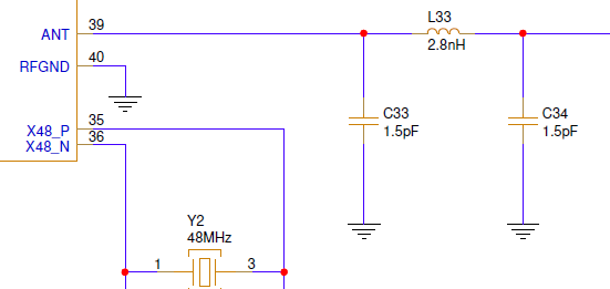
We understand that an output pi filter is required (C33, C34, and L33) to reduce the harmonic content of the output of the PA to match 50Ω of impedance. So we should just copy this design, correct?
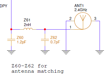
Looking at the LP-EM-CC2340R5 reference design there's also an antenna matching network for the Inverted-F PCB antenna. Is this needed for the MIFA? And if so, should we use the same values?
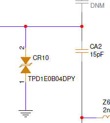
Finally, should we also include CA2 to block the DC bias voltage? And what is CR10 used for?
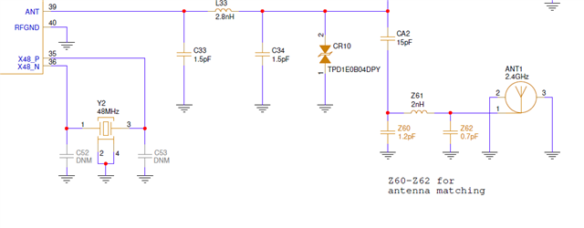
Here's the entire antenna design for reference:
Thank you,
Rob
