This thread has been locked.

If you have a related question, please click the "Ask a related question" button in the top right corner. The newly created question will be automatically linked to this question.

CC2745R10-Q1: Current consumption of VDDS in advertising mode

Part Number: CC2745R10-Q1

Tool/software:

Hello team,

I need to understand the current consumption of CC2745R10 , when the BLE is in advertising mode .This will help us to calculate system level sleep current for the complete ECU

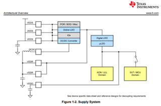
I am using the internal Buck regulator to supply VDDR

  • Darshan,

    Because of the variability of the BLE advertising mode settings it will be difficult to provide an accurate current consumption number for you. The best method to determine your current consumption is taking a LP-EM-CC2745R10-Q1 (link) board and loading the Basic BLE example project from the simplelink_lowpower_f3_sdk_8_40_00_61 SDK configured with your desired settings for advertising. You can then measure the current consumption of the board utilizing a power consumption analyzer or you can connect the LP to an LP-XDS110ET which can provide power consumption numbers of the LP while in operation, using Energy trace. 

    Regards,

    Andrew

  • Hello Andrew,

    Pin number30 DCDC_SW  when it will activated and what is the output voltage of the pin .

    Pin number  1 2 &34 output of DCDC SW is seriving as a input for GLDO - so what is the GLDO output voltage which will be generated internally

  • Darshan,

    The output voltage of the DCDC is trimmed to 1.5V. The DCDC is enabled during the bootloader initialization. The DCDC output is not an input for the GLDO. The GLDO is powered up by VDDS and can be configured to internally generate the 1.5V required for the VDDR pins 1, 2, & 34. If GLDO is used for VDDR, current consumption of the device will be higher than when the DCDC switcher is used. Please refer to section 1.5, section 6.3.1, and chapter 18 of the technical reference manual linked here

    Regards,

    Andrew

  • Hello Andrew,

    Thanks for the feedback it is much understood .

    1 .What are these VDDR pins ? and internally which blocks it is going to supply

    2. Why VDDR pins are connected with DCDC pin

  • Darshan,

    The VDDR pins are the supply pins for the RF core and need to be supplied either by the DCDC convertor or the Global LDO. For the lowest power consumption possible the DCDC convertor output must be utilized and must be connected to VDDR pins through the regulator inductor and cap. Connecting the DCDC to the VDDR pins places the DCDC and the Global LDO in parallel. When the DCDC is enabled, the Global LDO enable toggle logic only enables the Global LDO to power VDDR when the load on the DCDC reaches it's threshold. This helps reduce ripple on VDDR when the current draw is above the DCDC threshold. Once current draw drops below the DCDC threshold, Global LDO will deactivate and the DCDC regulator will again power VDDR. Please read chapter 18 of the technical reference manual linked here. This chapter provides the information on how these 2 regulators work together. 

    Regards,

    Andrew

  • Hello Andrew,

    it very much understood about the power architecture of IC ,have few queries w.r.t device operating states.

    • what will be the state of the IC when the device is in advertising mode ( Atcive ,Idle,standby)?

    • What is steps to be followed to put the IC into advertising mode ?
  • Darshan,

    When the device is in advertising mode, the device is Active.

    The easiest way to setup a device for advertising mode would be to follow the Basic BLE example provided in the SDK. The link below provides the Basic BLE project information and if you want to put the device into advertising mode, you should look at the README.html file and setup the device in a "Peripheral" role.

    https://dev.ti.com/tirex/explore/node?node=A__AICQamWzKKYvy-NaJbRh1Q__com.ti.SIMPLELINK_LOWPOWER_F3_SDK_BLE5STACK_MODULE__58mgN04__LATEST

    Regards,

    Andrew