This thread has been locked.

If you have a related question, please click the "Ask a related question" button in the top right corner. The newly created question will be automatically linked to this question.

CC2640R2F: Tri-state output mode

Part Number: CC2640R2F

Tool/software:

Im trying to set one of the DIO pins on a custom board with the CC2640R2F microcontroller as an output pin in the tri-state mode. In the technical reference manual, it says that (page 989) "By disabling the output buffer the corresponding I/O pin will be in the tri-state condition (high impedance). If nothing is driving the I/O to a valid logical level when the output buffer is disabled then disable the input buffer to avoid excessive current draw through the I/O input buffer." How exactly are the output and input buffers enabled/disabled? 

  • Hi Tamer,

    Section 11.6 of the TRM says "By default, the I/O driver (output) and input buffer (input) are disabled (tri-state mode) at power on or reset, and thus the I/O pin can safely be left unconnected (floating)."

    The output and input buffer settings exist in the IOCFGx register of the IO Controller for the pin of interest.  Here are the driverlib and TI Driver PIN (GPIO is also available) libraries for controlling the I/O settings.

    You can review the CC2640R2_LAUNCHXL.c gpioPinConfigs and BoardGpioInitTable structures for more information about the default pin configurations.  The examples configure unused I/Os for the lowest power consumption by default.

    Regards,
    Ryan

  • Hi Ryan,

    Thanks for your fast response and for providing the necessary libraries.

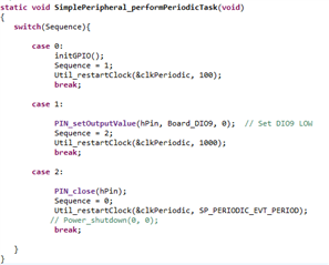
    I have implemented a solution in my Simple Peripheral project where DIO9 is set to LOW initially and then switched to a floating (tri-state) condition after a short delay, repeatedly toggling between these states.

    I’ve attached images of my implementation, including:

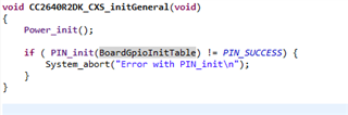
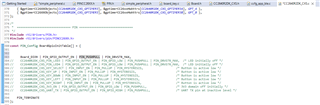
    • The Board GPIO initialization table which is used for initializing the pins when PIN_init is called in my main.c code.  

    • The periodic task that controls the LOW → FLOAT transition.

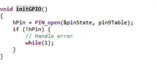
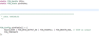
    • The initGPIO() function (which i defined) that simply sets up and opens the pin.

    Could you confirm if my approach is correct based on the way I open, set, and close the pin? Specifically, does calling PIN_close(hPin) properly transition the pin to a high-impedance state as expected? what would you do differently?

  • I don't have any immediate concerns with your application.  Is the output of this code not behaving as you would expect it to?

    Regards,
    Ryan