


Tool/software:
Hi,
I have a very simple program to enter power shutdown mode on a CC2340R52N0RGER SimpleLink MCU that is on a custom PCB board.
I am expecting a shutdown current consumption of below 1uA, which I have been able to achieve on the LP-EM-CC2340R5 LaunchPad development kit.
The VDDS input is 1.8V, and the measured current consumption during shutdown mode is 15uA. Increasing the voltage of VDDS only increases the current usage.
I can confirm that the device enters shutdown because it disconnects from the debugger. Current consumption is measured with the board not connected to any other peripherals.
The code is very simple and is adapted from the examples. The main_nortos.c code is below, the generated ti_driver_config.c is attached.
#include <ti/drivers/Board.h>
#include <ti/drivers/Power.h>
int main(void) {
Board_init();
Power_shutdown(0, 0);
while (1) {}
}
/*
 *  ======== ti_drivers_config.c ========
 *  Configured TI-Drivers module definitions
 *
 *  DO NOT EDIT - This file is generated for the CC2340R5RGE
 *  by the SysConfig tool.
 */

#include <stddef.h>
#include <stdint.h>

#ifndef DeviceFamily_CC23X0R5
#define DeviceFamily_CC23X0R5
#endif

#include <ti/devices/DeviceFamily.h>

#include "ti_drivers_config.h"

/*
 *  =============================== GPIO ===============================
 */

#include <ti/drivers/GPIO.h>

/* The range of pins available on this device */
const uint_least8_t GPIO_pinLowerBound = 3;
const uint_least8_t GPIO_pinUpperBound = 24;

/*
 *  ======== gpioPinConfigs ========
 *  Array of Pin configurations
 */
GPIO_PinConfig gpioPinConfigs[25] = {
    0, /* Pin is not available on this device */
    0, /* Pin is not available on this device */
    0, /* Pin is not available on this device */
    GPIO_CFG_NO_DIR, /* DIO_3 */
    GPIO_CFG_NO_DIR, /* DIO_4 */
    GPIO_CFG_NO_DIR, /* DIO_5 */
    GPIO_CFG_NO_DIR, /* DIO_6 */
    GPIO_CFG_NO_DIR, /* DIO_7 */
    GPIO_CFG_NO_DIR, /* DIO_8 */
    GPIO_CFG_NO_DIR, /* DIO_9 */
    GPIO_CFG_NO_DIR, /* DIO_10 */
    GPIO_CFG_NO_DIR, /* DIO_11 */
    GPIO_CFG_NO_DIR, /* DIO_12 */
    GPIO_CFG_NO_DIR, /* DIO_13 */
    GPIO_CFG_NO_DIR, /* DIO_14 */
    GPIO_CFG_NO_DIR, /* DIO_15 */
    GPIO_CFG_DO_NOT_CONFIG, /* DIO_16 */
    GPIO_CFG_DO_NOT_CONFIG, /* DIO_17 */
    GPIO_CFG_NO_DIR, /* DIO_18 */
    GPIO_CFG_NO_DIR, /* DIO_19 */
    GPIO_CFG_NO_DIR, /* DIO_20 */
    GPIO_CFG_NO_DIR, /* DIO_21 */
    GPIO_CFG_NO_DIR, /* DIO_22 */
    GPIO_CFG_NO_DIR, /* DIO_23 */
    GPIO_CFG_NO_DIR, /* DIO_24 */
};

/*
 *  ======== gpioCallbackFunctions ========
 *  Array of callback function pointers
 *  Change at runtime with GPIO_setCallback()
 */
GPIO_CallbackFxn gpioCallbackFunctions[25];

/*
 *  ======== gpioUserArgs ========
 *  Array of user argument pointers
 *  Change at runtime with GPIO_setUserArg()
 *  Get values with GPIO_getUserArg()
 */
void* gpioUserArgs[25];


/*
 *  ======== GPIO_config ========
 */
const GPIO_Config GPIO_config = {
    .configs = (GPIO_PinConfig *)gpioPinConfigs,
    .callbacks = (GPIO_CallbackFxn *)gpioCallbackFunctions,
    .userArgs = gpioUserArgs,
    .intPriority = (~0)
};

/*
 *  =============================== Power ===============================
 */
#include <ti/drivers/Power.h>
#include "ti_drivers_config.h"
#include DeviceFamily_constructPath(driverlib/ckmd.h)
#include DeviceFamily_constructPath(driverlib/pmctl.h)

extern void PowerCC23X0_standbyPolicy(void);


const PowerCC23X0_Config PowerCC23X0_config = {
    .policyInitFxn              = NULL,
    .policyFxn                  = PowerCC23X0_standbyPolicy,
    .startInitialHfxtAmpCompFxn = NULL,
};

#include <ti/drivers/Board.h>

/*
 *  ======== Board_initHook ========
 *  Perform any board-specific initialization needed at startup.  This
 *  function is declared weak to allow applications to override it if needed.
 */
void __attribute__((weak)) Board_initHook(void)
{
}

/*
 *  ======== Board_init ========
 *  Perform any initialization needed before using any board APIs
 */
void Board_init(void)
{
    /* ==== /ti/drivers/Power initialization ==== */

    Power_init();
    PowerLPF3_selectLFXT();
    PMCTLSetVoltageRegulator(PMCTL_VOLTAGE_REGULATOR_DCDC);


    /* ==== /ti/drivers/GPIO initialization ==== */
    /* Setup GPIO module and default-initialise pins */
    GPIO_init();

    Board_initHook();
}
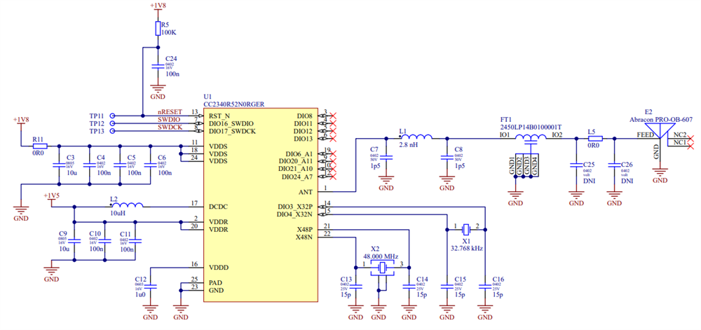
The hardware is also simple and follows the guidelines:
Please can anyone help me figure out what I am doing wrong?
Kind Regards,
Hristo

