This thread has been locked.

If you have a related question, please click the "Ask a related question" button in the top right corner. The newly created question will be automatically linked to this question.

LAUNCHXL-CC26X2R1: LAUNCHXL-CC26X2R1: SPI_POL0_PHA0 mode Single Transfer/Continuous Transfer

Part Number: LAUNCHXL-CC26X2R1
Other Parts Discussed in Thread: SYSCONFIG

Tool/software:

Hi Sir,

I am using the LAUNCHXL-CC26X2R1 board to communicate with an external L9963E IC via SPI.

My project uses the TI SPI Driver (SPI.h) from SimpleLink CC13xx CC26xx SDK

I have encountered an issue when operating in SPI_POL0_PHA0 mode (CPOL=0, CPHA=0):

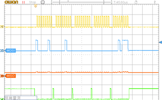
Even though I set transaction.count =5 , the CS pin is pulled high after each byte, causing the transfer to be split into multiple segments.

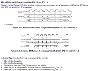
I am not sure if this behavior is related to the Single Transfer or Continuous Transfer modes mentioned in the TRM (Chapter 22.4.4.3), but I couldn't find any configuration option in the TI SPI Driver (SPI.h API) to change this behavior.

I would like to know where to change this setting—whether via an API, SysConfig, or by modifying the low-level driver source code.

  • Hi fan,

    The SPI peripheral on the CC26XX will behave in this manner and cannot be reconfigured.  For the end application you've described, I typically recommend that Three Pin Mode be selected in the SysConfig SPI module.  Then you will assign a generic GPIO to the CS pin and (de)activate it before and after the SPI transfer.  This is known as software-controlled chip select SPI usage.

    Regards,
    Ryan

  • Hi Ryan,

    Thanks for your reply!

    I have tried the 3-Pin mode with software-controlled CS, as you suggested.

    I manually control the CS pin using GPIO, and it does go low during the SPI transfer as expected.

    However, I still see that the clock signal has a gap after each byte (even when I set transaction.count = 5).

    It seems that the SSI peripheral itself still segments each byte, even though the CS pin remains low throughout the transfer.

    Interestingly, when I switch to CPOL=0, CPHA=1 (SPI_POL0_PHA1) mode, the clock signal is continuous and there are no gaps between bytes—the transfer works as expected.

    Unfortunately, my target device (L9963E) only supports CPHA=0, so I am unable to use this mode.


    Is there any way to configure the hardware SSI to maintain a continuous clock (without gaps) when using CPOL=0, CPHA=0 mode?


    Thanks for your help!

  • When you refer to the SysConfig SPI module, the "Min DMA Transfer Size" is set to 10 by default which directly influences whether a SPI transfer is large enough to use DMA instead of polling (i.e. delay for processing in between bytes).  What you are observing could be a tradeoff of the SPI TI Driver from not having enough bytes in the transaction.  You can thus choose to lower the Min DMA Transfer Size or increase the number of bytes per transaction.  I am not sure why the behavior changes when CPHA is one, however I would not expect the delay in between bytes to affect communication with your target device.

    Regards,
    Ryan