Other Parts Discussed in Thread: SYSCONFIG
Tool/software:
Hello, TI,
When the SPI communication method is changed from polling to DMA, data cannot be sent.
(Environment)
Software Product: SimpleLink Low Power F3 SDK (8.30.00.11_ea)
Board: CC2745R10-Q1 Development Platform
In the above environment, the SPI communication method was changed from polling to DMA.
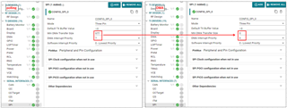
(Changes(Sysconfig))
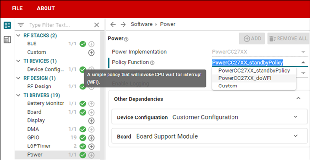
SERIAL INTERFACES -> SPI ->
Min DMA Transfer Size: 977 → 0
DMA Interrupt Priority: 7 → 6
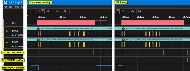
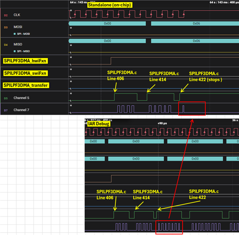
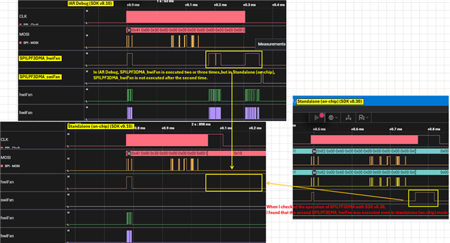
After making the above changes and debugging each,
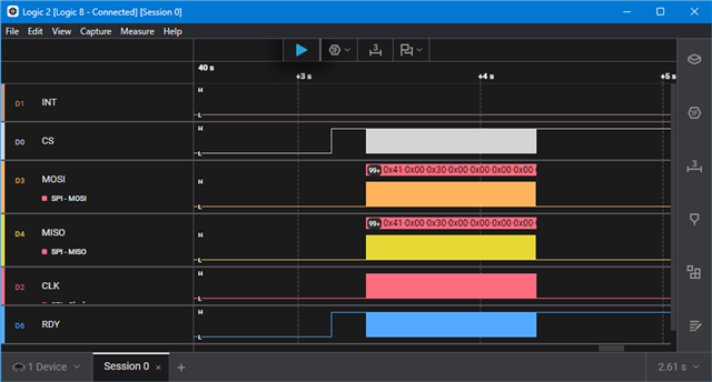
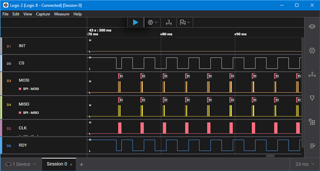
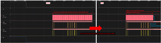
Before the change (polling): When trying to send 51 bytes of data, 51 bytes of data is sent. (Data transmission successful)
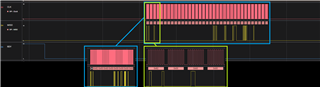
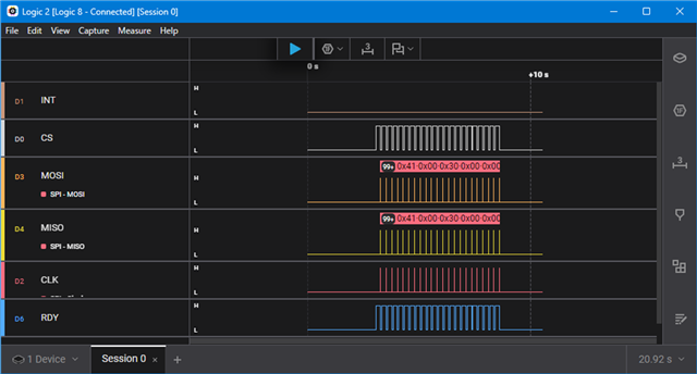
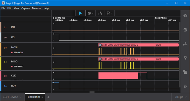
After the change (DMA): When trying to send 51 bytes of data, 35 bytes of data is sent. (Data transmission failed)
Why does this result?
Regards,
Sho