This thread has been locked.

If you have a related question, please click the "Ask a related question" button in the top right corner. The newly created question will be automatically linked to this question.

CC2652R7: Having Trouble with using the DIO_2 Pin as a GPIO

Part Number: CC2652R7
Other Parts Discussed in Thread: SYSCONFIG, ,

Tool/software:

Hi,
I am currently working on a project that requires uses two UART instances. I noticed that when i use DIO_2 as a RX pin for my UART , i don't get any UART message. When i looked into it using a LOGIC Analyzer, i only saw a high signal. Then i tried the same with another GPIO pin and they works without any error. Only problem is with the specific pin only. I was using a project zero template to do this, so I am aware that the display UART uses these pins, so I deleted the things related to the displayUART and checked. Then i checked with an empty project and I got the same result. I am new to this board so I'm unaware of somethings so please excuse me.


Thank you,
Bawantha

  • Hi !

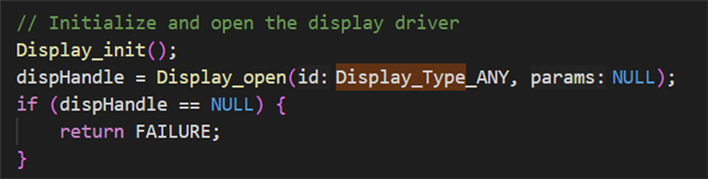
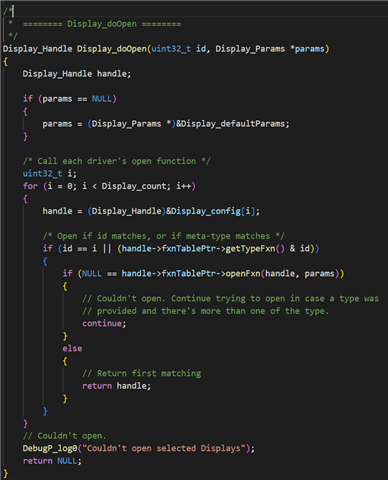
    When printing text, the software has to chose a UART instance it wants to use. In the case of the basic_ble project, the menu module used by the example opens a display driver instance with the setting "Display_Type_ANY", which will use the first display device it finds.
      

    In your case, the first display device will be your first UART device, CONFIG_Display_0.

    If you want to chose what display you want to use, you will need to open a display driver instance yourself and use the handle to this instance to call the UART write functions. You can find the guide and API on how to do this in this link.

    In short, your code will look like this :

    // Import the UART2 driver definitions
    #include <ti/drivers/UART2.h>
    
    // Open the UART
    UART2_Handle uart;
    uart_0 = UART2_open(CONFIG_UART2_0, UART2_config[CONFIG_UART2_0]);
    uart_1 = UART2_open(CONFIG_UART2_1, UART2_config[CONFIG_UART2_1]);
    
    // Write to the UART
    int16_t BUFSIZE = 2;
    int32_t status;
    uint8_t buffer[BUFSIZE] = {0x42, 0x18};
    size_t  bytesWritten;
    status = UART2_write(uart_0, buffer, BUFSIZE, &bytesWritten);
    status = UART2_write(uart_1, buffer, BUFSIZE, &bytesWritten);
    
    // Close the UART
    UART2_close(uart);

    Kind regards,
    Maxence

  • Hi,
    Thank you for taking time to reply. But I think there's been a misunderstanding. I have a UART configured to the pins DIO2 (TX) and DIO3 (RX) from my CC2652 microcontroller. I am trying to communicate with an ESP32 and The message is being transferred to the ESP32 but when I try to send back a message to the CC2652, I dont get the message. Then I looked into the RX line using a LOGIC, I can see that when the RX line is connected to CC2652, all we get is a HIGH signal but when i disconnect that line from the CC2652 side , ESP32 is indeed is sending the message.
    Becuase of this tried using the DIO3 as a GPIO pin, but it also failed.

  • Hi !

    First of all, I would check if the pin you are connected to is indeed DIO 3 and not another one.

    Are you using a LaunchPad with the CC2652 or are you using a custom board ? Are you connecting a LaunchPad and XDS110 in your setup ? If not, you can try to set "Use Hardware" to "None" in SysConfig and then hover on the warning and select "Use a custom board" link.

    Kind regards,
    Maxence

  • Hi,
    I tried on a LaunchPad and I have indeed set "Use Hardware" to "None" in sysconfig

  • Are you using a LaunchPad with the CC2652 or are you using a custom board ?

  • I am using a LP-CC2652R7 — CC2652R7 LaunchPa

  • Hi, did you find any solution for this?

  • Hi,

    If you are using a LaunchPad with the CC2652R7, chances are that you are using the XDS110 connected to it to flash your firmware.
    When using the XDS110, you might have connected the RXD and TXD pins, which connected to DIO2 and DIO3. These pins are used to communicate by UART between your computer and the board.

    You could try removing the jumper between those pins in order to release the connection to DIO2 and DIO3 (like in this photo).

    If this did not work, you could try to remove all the jumpers except ground and power, and to flash your device only using JTAG.

    Kind regards,
    Lea