CC2340R5-Q1: Power consumption issues in SHUTDWON mode

Part Number: CC2340R5-Q1
Other Parts Discussed in Thread: SYSCONFIG

Tool/software:

Hi team

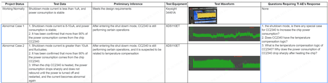
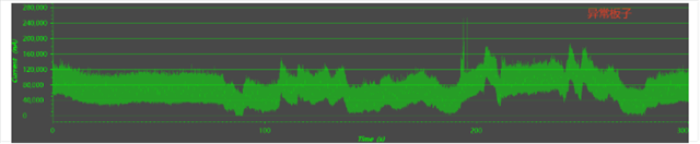
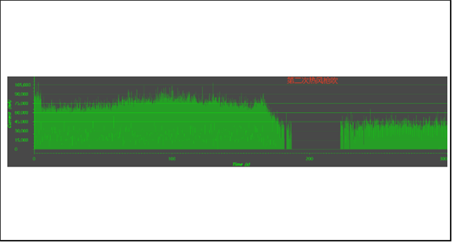
I have found that some chips have power consumption issues and need help to analyze them. The test data is as follows:

SDK:8.10

question:

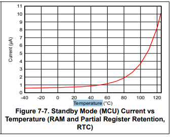
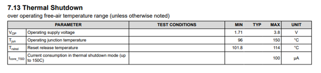
1. the shutdown mode, is there any special case for CC2340 to Increase the chip power consumption?

2. Does CC2340 have the temperature compensation logic?

3. What is the temperature compensation logic of CC2340? Why does the power consumption of CC2340 drop sharply after heating the chip?

  • Hello,

    I apologize for the delay here and have assigned an expert to this thread.

    Best,

    Nima Behmanesh

  • Jiang,

    1. How many abnormal case 1 boards have you seen and how many abnormal case 2 boards have you seen?

    2. How many normal boards have you seen?

    3. What temperature are you operating at and at what temp to you see the power consumption drop and the device won't recover until power cycled.

    Temp compensation for this device ensures RF output power is consistent over temperature and does not apply to power consumption when in shutdown mode. It is expected for current to increase when temperature increases. Also keep in mind that the CC2340R52-Q1 device has a thermal shutdown feature.

  • 1.There are a total of 1000 boards, with 3 boards in Case 1 and 20 boards in Case 2.

    2.Configure the SWD interface as a digital input or low-level output, and the abnormal shutdown current phenomenon in cases 1 and 2 disappears, with a current less than 200nA.

    3.External 10K resistor pull-down was applied to the clk and data signals of SWD, but the abnormal shutdown current still exists in cases 1 and 2.

    question:

    1. Why can't SWD be configured as high impedance? It must be configured as low level to ensure that the chip shutdown current is normal
    2. What is TI's recommended configuration for GPIO, SWD, and crystal oscillator input/output pins of CC2340 in shutdown mode
    3. When the SWD is configured with high resistance, the shutdown current will dynamically fluctuate. At this time, heating the chip with a hot air gun (less than 80 degrees Celsius), why does the sleep current suddenly decrease? Is there any temperature compensation mechanism inside the chip?

  • Jiang,

    By default SWDIO has an internal pull-up and SWCLK has an internal pull-down enabled. We don't recommend adding an external pull-down to SWCLK as this will increase your current consumption due to the internal pull-up on SWCLK.

    On your board design, what do you have connected to these 2 pins (SWCLK and SWDIO)? Can you share your schematic? Knowing what is tied to these pins may explain why configuring these pins to high impedance results in abnormal case 1 or 2.

    Thanks,

    Andrew

  • Our board's SWD pin is not connected to anything, it only leads out the test point

  • Latest test conclusion: Add pull-down resistor to SWCLK, pull-up resistor to SWDIO, and pull-up resistor to serial port RX. The phenomena in Case 1 and Case 2 have disappeared, and the current is below 1uA

  • Jiang,

    Yes adding a pull-down resistor to SWCLK and pull-up resistor to SWDIO is acceptable and I'm glad this fixed your issue. Can you tell me what version of the SW SDK you're using?

    Thanks,

    Andrew

  • simplelink_lowpower_f3_sdk_8_10_01_02

  • By configuring SWCLK and SWDIO as input pull-up and disabling UART's TX and RX through software, the above problem can also be solved.

  • I would like to know what could be the possible cause of our problem. Can you help evaluate if there are any other risks associated with my changes

  • Jiang,

    simplelink_lowpower_f3_sdk_8_10_01_02 does not by default enable the pulls on SWCLK and SWDIO. This was not implemented until SDK release 8.40.00.61 (Dec 20, 2024). If you build your firmware with the 8.4 SDK the pulls on SWCLK and SWDIO will by default get enabled and you won't have this issue. 

    You also mentioned that you had to disable your UART pins. Can you share what you have tied to the UART lines and how you have them configured in sysconfig?

    Thanks,

    Andrew

  • The resistor R203 is not attached

  • GPIO_setConfig(CONFIG_GPIO_UART2_0_TX, GPIO_CFG_NO_DIR);
    GPIO_setConfig(CONFIG_GPIO_UART2_0_RX, GPIO_CFG_NO_DIR);

    disabling UART's TX and RX through software

  • Jiang,

    1. So if you only add an internal pull-up to SWDIO and a pull-down to SWCLK, how do the devices behave, is the current draw still high in shutdown mode?

    2. What about if you only disable the UART pins but leave SWDIO and SWCLK alone, is the current draw still high in shutdown mode? 

    3. Are the UART TX and RX lines floating during your testing?

    4. Was your SW changing the configuration of the UART lines in the application before you made the change to disable the GPIOs? If so what configuration change was the SW applying previously?

    Regards,

    Andrew