This thread has been locked.

If you have a related question, please click the "Ask a related question" button in the top right corner. The newly created question will be automatically linked to this question.

CC2340R5: CC2340R5: UART FOTA Using MCUBoot & OAD Off chip example code combination.

Part Number: CC2340R5
Other Parts Discussed in Thread: SYSCONFIG, UNIFLASH

Hello TI team,

I'm using BLE CC340R5 Module. 

I'm using SDK simplelink_lowpower_f3_sdk_8_40_02_01.

I want to perform BLE FOTA using UART file transfered through external device. 

I've gone throguh TI documents & the OAD example code, but I'm not sure if I can use the combination of MCUBoot example code and BLE OAD Offchip example code for this operation. 

Can you confirm if this can be done, if yes 1.What things need to be taken care of?

2.How to trigger MCUBoot after completion of file transfer?

3.How & where the old bin is saved, if in NVM how MCUboot reads the addresses?

4.How to inform MCUBoot about new bin availabiity in NVM & its address?

5.Can we use the OAD Offchip example code in peripheral + central mode?

6.How to stop the interrupts & tasks in BLE code?


Thanks & regards,

Rushikesh.

  • Hi Rushikesh,

    Thank you for reaching out!

    1.What things need to be taken care of?

    Yes, they are built as an integrated system in the F3 SDK. The basic_ble_oad_offchip example for LP_EM_CC2340R5 is already configured to rely on MCUBoot.

    For UART file transfer: The basic_ble_oad_offchip example uses BLE as the transport to write image blocks into external flash. If you want to use UART, you will need to implement a custom UART receiver that writes the signed image to the external flash secondary slot at the correct address. The MCUBoot bootloader logic (boot decision, copy, verify) remains unchanged.

    2.How to trigger MCUBoot after completion of file transfer?

    Call HapiSbSetId(3) then SystemReset() and this should cause the new image to be taken.

    #ifdef SECURE_BOOT
    HapiSbSetId(3); // Signals secure boot: new image is ready in secondary slot
    #endif
    SystemReset(); // Triggers warm reset; MCUBoot runs on next boot
    HapiSbSetId() writes a persistent flag in the 3V3 domain that survives the reset. On the next startup, the ROM checks this flag, hands control to MCUBoot, which then validates and boots the new image.

    3.How & where the old bin is saved, if in NVM how MCUboot reads the addresses?

    The old binary stays in the internal flash until after the device resets and MCUBoot overwrites it with the newly downloaded image. The addresses are compile-time configured in the mcuboot config files.l

    4.How to inform MCUBoot about new bin availabiity in NVM & its address?

    Addresses are statically set through SysConfig. There is no dynamic addresses detection necessary.

    5.Can we use the OAD Offchip example code in peripheral + central mode?

    Yes, OAD supports multirole with no issues.

    6.How to stop the interrupts & tasks in BLE code?

    I would not recommend disabling the interrupts in BLE for OAD. If you are receiving the OAD image over BLE then letting the OAD task handle everything is the best path. If you would like to go the UART path, then I would recommend re-using as much of the OAD state diagram as possible.

    That said, if you plan to do OAD via UART, then I think a better solution will be to use the serial bootloader. This allows you to simply put the device into bootloader mode and send the image via UART to be automatically flashed onto the device. I recommend referencing the bootloader section of the TRM to see if this solution makes sense for your use-case.

    Best Regards,

    Jan

  • Hello Jan,

    Thanks for your valuable inputs!

    I just want to update you that I'm using a custom board & the CC2340R5 chip is mounted on it interfaced with microcontroller through UART peripheral.

    Currently we don't have the external flash available, so I've to switch to On chip or Dual image example code.

    So in that case, I guess above all things remain same, is it?

    Just few more queries I have:

    1.In 2nd query from above, HapiSbSetId(3); I guess this API inform MCUBoot about firmware availability in secondary slot. 

    Does this call remains same if the FW is available in internal flash?

    2.As you said that the old bin stays in internal flash, is this also applicable to on chip/dual image example code? 

    3.It makes sense to use a custom serial bootloader. But there is a major drawback of directly flashing bin file in case of On chip/Dual image logic.

    5.Can you help me to understand how to put the device into bootloader mode?

    5.Also, to develop a custom bootloader what things are necessary can explain? 

    6.Can I use the MCUBoot example code to develop this serial bootloader? Will replace the file transfer mechanism with custom UART FTP.

    Thanks & Regards,

    Rushikesh.

  • Hi Rushikesh,

    1.In 2nd query from above, HapiSbSetId(3); I guess this API inform MCUBoot about firmware availability in secondary slot. 

    Does this call remains same if the FW is available in internal flash?

    Correct. The same procedure and API call occurs to signal a new image is ready in the secondary slot.

    2.As you said that the old bin stays in internal flash, is this also applicable to on chip/dual image example code? 

    To clarify, the old image stays in the primary slot until reset. After reset, the new image overwrites the old image and the old image is replaced by the new image. If you would like to keep the old image, then you would need to develop an image backup system built on-top of mcuboot.

    3.It makes sense to use a custom serial bootloader. But there is a major drawback of directly flashing bin file in case of On chip/Dual image logic.

    5.Can you help me to understand how to put the device into bootloader mode?

    5.Also, to develop a custom bootloader what things are necessary can explain? 

    6.Can I use the MCUBoot example code to develop this serial bootloader? Will replace the file transfer mechanism with custom UART FTP.

    I would highly recommend using the serial bootloade that is built-into the device instead of developing your own. You may enable the serial bootloader through syscfg and blank devices have it enabled by default. You can configure the device to enter the serial bootloader via a specific IO's state. Within the SBL, you can then flash an image via UART and perform simple flash operations via UART as well. I would recommend referencing the ROM Bootloader section of the TRM. If a custom bootloader is truly necessary, then you may build on top of mcuboot and use that as your custom bootloader.

    Best Regards,

    Jan

  • Hello Jan,

    I went through the TRM of CC23xx and understood that we can also use serial bootloader & flash the image using external interface through UART/SPI.

    I have query below:

    1.If during file transfer power cut down, then will the device get stuck into the ROM bootloader or is there any FSM already defined?

    2. In TRM section 8.5.4, it is mentioned that we've to send CCFG content after image transfer completed.

        How to exactly save & share this CCFG content? File type?

    3. What type of image need to be sent to ROM bootloader, .bin or .hex?

  • Hi 

    1.If during file transfer power cut down, then will the device get stuck into the ROM bootloader or is there any FSM already defined?

    The ROM bootloader does not persist any transfer state across a power loss, so in other words upon next power-up you have no memory or record of what happened in the previous run. On the next power-up, the device will re-enter the bootloader if your trigger pin is still asserted (or if the flash has no valid app). From there, the host simply restarts from the beginning: issue BLDR_CMD_CHIP_ERASE, then restart the download sequence.

    One important note: If you use BLDR_CMD_DOWNLOAD_CRC (recommended, per TRM §8.5.3.8), a CRC check is performed once all bytes are received. If the transfer was interrupted and the CRC never completes, the partially-written content is automatically erased when the next chip erase runs. So there is no risk of the device being bricked by a partial write — just retry from step 1 (chip erase + download).

    2. In TRM section 8.5.4, it is mentioned that we've to send CCFG content after image transfer completed.

        How to exactly save & share this CCFG content? File type?

    The CCFG is a 2048-byte binary region at address 0x4E020000. It is generated by SysConfig and compiled into your application's .out file as the .ccfg linker section.

    To extract it as a standalone binary, use objcopy in your post-build step:

    arm-none-eabi-objcopy -O binary --only-section=.ccfg myapp.out ccfg.bin


    This ccfg.bin is then sent via the standard SBL packet protocol (steps 6–7 in TRM §8.5.4):

    • BLDR_CMD_DOWNLOAD_CRC with startAddress=0x4E020000, length=2048, and the CRC of the CCFG bytes
    • Followed by BLDR_CMD_SEND_DATA chunks (252 bytes max each)

    The format is raw binary, so just sending the raw hex will transfer the image. The protocol carries address information separately in the DOWNLOAD command, not embedded in the data.

    3. What type of image need to be sent to ROM bootloader, .bin or .hex?

    The binary would be the correct one (.bin).

    Best Regards,

    Jan

  • Hello Jan,

    Thanks for your support. 

    Let me check & get back to you on above points.

    Thanks & regards,

    Rushikesh.

  • Hi Rushikesh,

    No problem! Glad to help!

    Best Regards,

    Jan

  • Hello Jan,

    I have a follow up question for you:

    1.It is mentioned that we can enter into ROM bootloader by asserting backdoor pin.

    I consider that we should pull this pin to low & toggle the RESET pin.

    But, this needs to be triggered by BLE application itself? or is it need to be handled with the help of external interface?

    2.Can we configure any GPIO as a backdoor pin/trigger pin to enter into bootloader mode? Or is it a fixed GPIO?

    Actually, to my controller we've connected DIO11 and I can use/access only this GPIO as a trigger pin.

  • Hi,

    1.It is mentioned that we can enter into ROM bootloader by asserting backdoor pin.

    I consider that we should pull this pin to low & toggle the RESET pin.

    But, this needs to be triggered by BLE application itself? or is it need to be handled with the help of external interface?

    The bootloader pin may be configured through syscfg (both in terms of which pin you want to use and if you want it to trigger on high or low). The IO will need to be set to the trigger value by something external to the MCU and the MCU must be reset. Upon reset, the MCU will look at the bootloader pin, read its value, and if it is in the trigger value, then the bootloader will load. No SW changes or anything are needed besides configuring the device to allow the bootloader through syscfg. No application code changes are necessary.

    2.Can we configure any GPIO as a backdoor pin/trigger pin to enter into bootloader mode? Or is it a fixed GPIO?

    Actually, to my controller we've connected DIO11 and I can use/access only this GPIO as a trigger pin.

    It should be any GPIO. You can initiate a reset from within the application by calling the Reset API, but the trigger pin must be driver by something external.

    Best Regards,

    Jan

  • Hello Jan,

    In syscfg, for example I've configured a GPIO (DIO11) like a normal GPIO & set its trigger value as given below:

    How the bootloader will know about this particular GPIO that it is configured as a trigger pin/boot pin?

    Best Regards,

    Rushikesh.

  • Hi Rushikesh,

    This setting is set in the CCFG of the image which the bootloader looks at upon every boot and this is how it knows which IO to look at and what is the target value.

    Best Regards,

    Jan

  • Hello Jan,

    Configured below setting. With this setting ROM bootloader now knows that I've configured DIO11 as trigger/backdoor and using index = 1 which means I've configured DIO12 DIO13 as UART Rx, Tx pins. So that the ROM bootloader sends me ACK/NACK on this UART channel.

    Steps I followed (All on CC2340R5 launchpad): 

    1. Pull Trigger pin to LOW - connected to GND.

    2. Give reset.

    3. Release after ~500ms-1sec.

    4. Send 0x5555 on UART

    5. Wait for ACK/NACK.

    6. Received ACK as 0x00CC.

    7. Sent PING command as 0x032020

    8. Received 0x00CC.

    I was expecting this flow from you. But anyway, I'm able to enter into ROM bootloader.

    Can you tell me how CRC is calculated for the command flow given in TRM section 8.5.4?

  • As you confirmed earlier that we need to send .bin to ROM bootloader. Right now, the basic example code creates a .hex file after compilation. 

    Is there any possible way get/generate the same image in .bin format?

  • Hi Rushikesh,

    Can you tell me how CRC is calculated for the command flow given in TRM section 8.5.4?

    The CRC is the standard IEEE CRC-32 process. I believe it should be the same as the binascci.crc32() function in Python so you should be able to use that as a reference. This value goes into bytes 9–12 (MSB first) of the BLDR_CMD_DOWNLOAD_CRC packet. The bootloader recalculates the same CRC over all received BLDR_CMD_SEND_DATA bytes and if there is a mismatch it returns BLDR_CMD_RET_CRC_FAIL (0x45) and immediately erases the partial write. Note that you need to calculate and send CRC separately for the app image (steps 4–5 in §8.5.4) and again for the CCFG (steps 6–7).

    Is there any possible way get/generate the same image in .bin format?

    Yes, use tiarmobjcopy which is bundled with CCS TI Clang. You need two separate .bin files since the app and CCFG are sent to different addresses:

    • App binary (sent to 0x00000000):

    tiarmobjcopy myapp.out --output-target binary myapp_app.bin --remove-section=.ccfg
    

    • CCFG binary (sent to 0x4E020000):

    tiarmobjcopy myapp.out --output-target binary myapp_ccfg.bin --only-section=.ccfg

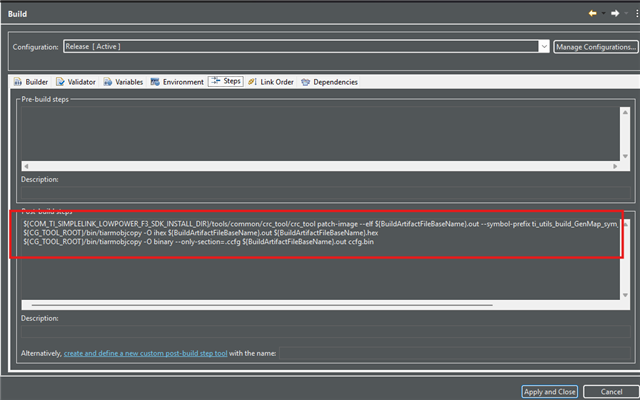
    You can add both as post-build steps in CCS under Project Properties → Build → Steps → Post-build steps. Use `${CG_TOOL_ROOT}/bin/tiarmobjcopy` instead of a hardcoded path. This is the same approach already used by the basic_ble_oad_offchip example in the SDK.

    Best Regards,

    Jan

  • Hello Jan,

    Thanks for your response.

    As per TRM, I'm trying to verify file transfer through UART from external interface. 

    I want to send the .bin file using commands given in TRM section 8.5.4

    Followed below command sequence, the chip is getting erased successfully.

    But while sending BLDR_CMD_DOWNLOAD or BLDR_CMD_DOWNLOAD_CRC, I'm always getting NACK from ROM bootloader.

    I did generate CRC using IEEE 32-bit CRC & used the same in the BLDR_CMD_DOWNLOAD_CRC command.

    Command sequence: 

    1]Initially as per example flow sent only BLDR_CMD_DOWNLOAD_CRC after chip erase.

    (13:30:44.677) (11.432) (<<) 55h 55h (2)

    (13:30:44.812) (0.135) (>>) 00h CCh (2)

    (13:30:46.112) (1.300) (<<) 03h 20h 20h (3)

    (13:30:46.245) (0.132) (>>) 00h CCh (2)

    (13:30:49.092) (2.847) (<<) 03h 24h 24h (3)

    (13:30:49.211) (0.119) (>>) 00h CCh (2)

    (13:30:52.522) (3.311) (<<) 0Dh 27h 00h 00h 00h 00h 00h 03h 6Eh F9h A9h 71h B4h CAh 3Ah (15)

    (13:30:52.683) (0.160) (>>) 00h 33h (2)

    0D - Length

    27 - Cmd ID

    00h 00h 00h 00h - Program address

    00h 03h 6Eh F9h - Program size

    A9h 71h B4h CAh - CRC

    3Ah - Checksum (Not sure if this needed, because getting same response with or without checksum)

    2]Then tried with sending BLDR_CMD_DOWNLOAD first, as I feel this is the correct expected sequence.

    (15:17:11.009) (3:11.600) (<<) 55h 55h (2)
    (15:17:11.148) (0.138) (>>) 00h CCh (2)
    (15:17:11.998) (0.850) (<<) 03h 20h 20h (3)
    (15:17:12.163) (0.165) (>>) 00h CCh (2)
    (15:17:14.064) (1.900) (<<) 03h 24h 24h (3)
    (15:17:14.197) (0.133) (>>) 00h CCh (2)
    (15:17:16.227) (2.030) (<<) 09h 26h 00h 00h 00h 00h 00h 03h 6Eh F9h C5h (11)
    (15:17:16.366) (0.138) (>>) 00h 33h (2)

    NOTE: Tried sending bytes in little endian also, for which getting NACK there as well.

    But I'm still getting NACK. Not sure what is missing from my side here.

    I'm attaching the .bin file also which I want to send to the ROM bootloader.

  • Also after hitting any command if I give BLDR_CMD_GET_STATUS command, ROM bootloader gives no response in return. 

    In fact, it does not respond to any other command after that. 

    What's the issue here?

    Can you confirm what's the timeout for each command is?

  • Hi Rushikesh,

    But while sending BLDR_CMD_DOWNLOAD or BLDR_CMD_DOWNLOAD_CRC, I'm always getting NACK from ROM bootloader.

    The issue is the packet framing. The CC23xx ROM SBL packet format is defined in TRM §8.5.1.1 as:

    [SIZE][CHECKSUM][DATA bytes...]
    

    where SIZE = number of data bytes + 2, CHECKSUM = 8-bit sum of all data bytes (mod 256), and DATA starts with the command byte. Your packets have the checksum and command byte in swapped positions, and the SIZE field is missing the +2.

    Your DOWNLOAD_CRC packet:
        0D  27  00 00 00 00  00 03 6E F9  A9 71 B4 CA  3A
            ^cmd here (wrong)                           ^checksum here (wrong)
        ^size=13 (wrong)

    Correct DOWNLOAD_CRC packet:
     
        0F  29  27  00 00 00 00  00 03 6E F9  A9 71 B4 CA
        ^   ^   ^cmd
        |   checksum = 0x29 (sum of 0x27+0x03+0x6E+0xF9+0xA9+0x71+0xB4+0xCA mod 256)
        size = 0x0F = 15 (13 data bytes + 2)
    For DOWNLOAD (0x26) on the same image:
     
        0B  90  26  00 00 00 00  00 03 6E F9
        size = 0x0B = 11 (9 data bytes + 2), checksum = 0x90
    One more note: BLDR_CMD_GET_STATUS is 0x21, not 0x24. The 0x24 packets you sent were BLDR_CMD_CHIP_ERASE (which is why the erase succeeded). The correct GET_STATUS packet is 03 21 21.
     

    Also after hitting any command if I give BLDR_CMD_GET_STATUS command, ROM bootloader gives no response in return. 

    After a packet with a wrong SIZE byte is received, the UART receive buffer on the bootloader becomes desynchronized — it read the wrong number of bytes and is waiting for data that will not arrive correctly. No subsequent command will be parsed regardless of waiting. There is no per-command timeout that will recover this; you must do a full hardware reset: de-assert the trigger pin, toggle RST, re-assert the trigger pin, then restart from the autobaud sync (55 55).
    Best Regards,
    Jan
  • Hi Jan, 

    Thanks for your response I resolved this issue yesterday. 

    Found that the frame format was incorrect. It took time for me to understand the frame format exactly because in TRM it is not clearly given. 

    The example also only shows command sequence not the frame format.

    The TRM says length = total number of data bytes + 2

    But is the command ID, checksum included in data bytes or not that is not mentioned anywhere. 

    I did follow the sequence as below:

    And it is working now. Just confirm is it correct?

    Now, I'm able to send the complete .bin file through a script to bootloader. Need to verify the CCFG file also by sending it after main .bin.

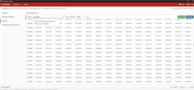
    I confirmed the bin is flashed using uniflash to read the memory till the address I sent to bootloader.

    Request you to confirm if I'm going in the right direction.

    Regards,

    Rushikesh.

  • Hi Rushikesh,

    Glad to hear! Yes, your commands look correct to me. :)

    Best Regards,

    Jan

  • Hello Jan,

    I did flash the .bin file into the ROM bootloader successfully. 

    Followed sequence of trigger pin & reset pin also to jump to application.

    But after flashing the bin, it is not working it seems.

    The device is not advertising nor it does print anything on console. I believe that the main binary & CCFG bin I created using post build steps does not work or got corrupted.

    Can you please tell me exact steps to generate .bin file both main code & CCFG? As previously you mentioned about CCFG.bin that it could be generated using objcopy.

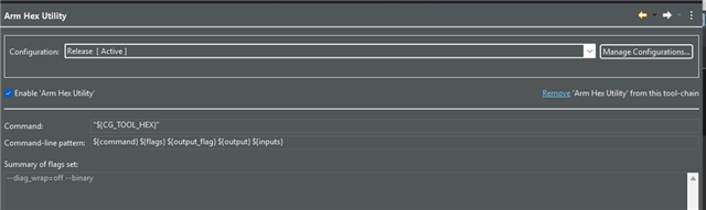
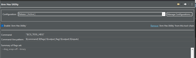
    Below is settings I did for it. 

    Maybe I guess we need to set memory range as well for the .bin we want to create, isn't it? 

  • Hi,

    To confirm, are you sending as mass erase after flashing the CCFG? If so, then that is erasing the CCFG as well. Do not send a mass erase between flashing the images as this will erase any content that was written to the flash banks.

    Best Regards,

    Jan

  • No actually I was flashing incorrect .bin file. I did change the settings to use the objcopy to get correctly generated .bin files of both App & CCFG.

    After flashing those bin files now it is working properly. 

    One more thing is, on Evk we have 40 pin packaged chip and on my custom board we have 24 pin (RGE) package. 

    So, on custom board the same pin DIO11 or a different one DIO8 will work the same way as boot pin? Or do I have to configure any other GPIO? 

    Regards,

    Rushikesh.

  • Hi Rushikesh,

    Sorry for the delay. I was out of office unexpectedly. Glad to hear that you were able to resolve the issue! Regarding the package, for the RGE, the default pins should be DIO20 and DIO6 for UART RX/TX. You may switch it to one of two other configurations for UART. The pin trigger may be any DIO.