A related question is a question created from another question. When the related question is created, it will be automatically linked to the original question.
If you have a related question, please click the "Ask a related question" button in the top right corner. The newly created question will be automatically linked to this question.
Thanks for the i2C files. I still have a few questions and I am a little confused. I am using the Cc2541 also.
FIRST: what do I set I2CCFG, I2CSTAT, etc to. I know they are at the addresses 0x6230-0x6235 but when I use a "#define I2CCFG 0x6230" I get compile errors such as "expression must be a modifiable value". I am sure it is operator error and I have the syntax incorrect. What do I set these address values to. There were not in the files you attached.
SECOND: hal_driver.pdf has the following definition for halI2cinit function. Am I using the correct I2C files. The prototype in your attached file is "void HalI2CInit(uint8 address, i2cClock_t clockRate)" not what is shown below in the document. just checking to make sure I have the correct I2C files.
11.1 HalI2CInit () 11.1.1 Description This I2C initialization function is called once at the startup. This function has to be called before any other I2C functions can be called. It enables I2C hardware resources to be initialized with both required and optional parameters. 11.1.2 Prototype void HalI2CInit (void) 11.1.3 Parameter Details None.
thanks for your help, I am coming up to speed quickly as we have some very tight schedules.
1. The beauty of the hal_i2c.c module is that it abstracts direct access to the physical I2C registers, so you should not need to think about them and just work with the API function calls.
2. Sorry, I don't know about the .pdf file you mention. For the API provided by the hal_i2c.c module, just peruse the hal_i2c.h file.
1. If you do not define I2CCFG and all of the others it will not compile. They are not defined anywhere. I found that you must define them to "#define I2CCFG XREG(0x6230)" and so on for all of the others. It compiles and I stepped it through in assembler and it is indeed writing and reading at the correct I2C addresses. but since I have the CC2540 (CC2541 is in the mail) there is no I2C block at these addresses and all reads and writes are NOPS basically.
2. the file "hal driver api.pdf" is located in C:\Texas Instruments\BLE-CC254x-1.2\Documents\hal that comes with the release.
Unfortunately I cannot actually run and test the I2C code since I have the CC2540 EM module in the SmartRF05 evaluation board Rev 1.8.1. The CC2541 EM module is due to arrive shortly.
My question is when the CC2541 EM module arrives can I just plug it into the smartRF05 board and run the sample programs (with the CC2541 configurations of course). If so how can I test the I2C capability of the CC2541 with the smartrf board. There are no files in the 1.2 release that have any reference, use, or mention of I2C at all. We must use the CC2541 since we have a requirement to interface to I2C devices. I can write the code and compile it but I am not sure how I can run it and debug it when I get the CC2541 EM module.
The I2C registers (like all peripheral registers for any SOC) are defined in the target-specific include file that is bundled with the IAR IDE. So when you open a CC2541 project and do a global search for I2CCFG in all include files, you will see it defined in ioCC2541.h:
The SmartRF05EB has the I2C pins on the debug headers, so you will jumper wire to whatever I2C device you want to talk to, providing the pullups to Vdd via resisitors that the I2C specification requires on any I2C bus.
This cleared things up. I have removed my definitions and only added I2C reference in the CC2541 configuration. I passed on the connection information to the HW designer so we can debug our I2C device with the CC2541 on the smartRF board when teh CC2541 arrives.
I am working with the I2C drivers that I downloaded from this thread, and I have attempted to effect a master mode repeated start, but could not. The CC2541 User's Guide, Table 20-3, specifies that after writing a byte in master transmit mode and receiving the slave ack, the status register will be 0x28, and a possible next step is to set the STA bit to effect a repeated start.
Unfortunately, I cannot put a scope on the I2C bus as I am working with a closed up system. But I can tell you that I used the debugger to step through and run through many different attempts to effect the restart, and the status register does not change from 0x18 - it never goes to the expected status of 'mstRepStart = 0x10' nor even to 'mstStarted = 0x08'.
At the end of the HalI2CWrite() function, I replaced the I2C_STOP() macro with this (copied from the I2C_STRT() macro:
At the NOP, the I2CSTAT register was not an expected value. On a side note, I inserted nop's in between every line and saw that programatically clearing the I2C_SI bit did not show up in the register watch window, but manually clearing the bit from that window succeeded in setting it to zero.
So could you possibly share the code that you used to prove out this I2C peripheral - I'm sure that I could dig through it and find the unit-test for master mode repeated-start.
I apologize for turning this thread into a run-on topic, but I posted this last week and got no responses:
some devices REQUIRE a repeated start. This is part of the I2C protocol. It differs from a normal i2C Write (followed by a I2C Stop) and then an I2C Read. It is a I2C Write with NO I2C stop. The stop is replaced with a I2C start (thus the term repeated start). The device I am working with now requires an I2C start. The normal hal_i2c.c write followed by a read will always return 0. The device will not operate properly.
Can you use the pieces that are suggested here to create a new hal_i2c.c read_with_repeated_start.
Did this ever get resolved? We're having the same issue.
Writing registers to our i2c device works fine, but when we want to read multiple bytes from a specific address, it always reads from an offset of zero. We got lucky since the registers we wanted to read just happened to be at 0x01, 0x02, and 0x03, (so we just read 4 bytes) and threw away the first one, but now, that is no longer the case and we'd really like to get this to work.
See code snippet below from our driver file for the mma8453. And attached hal_i2c.c that we pulled in, I think from the same source as this thread.
/**************************************************************************************************
  Filename:       hal_i2c.c
  Revised:        $Date: 2012-09-21 06:30:38 -0700 (Fri, 21 Sep 2012) $
  Revision:       $Revision: 31581 $

  Description:    This module defines the HAL I2C API for the CC2541ST. It
                  implements the I2C master.


  Copyright 2012 Texas Instruments Incorporated. All rights reserved.

  IMPORTANT: Your use of this Software is limited to those specific rights
  granted under the terms of a software license agreement between the user
  who downloaded the software, his/her employer (which must be your employer)
  and Texas Instruments Incorporated (the "License").  You may not use this
  Software unless you agree to abide by the terms of the License. The License
  limits your use, and you acknowledge, that the Software may not be modified,
  copied or distributed unless embedded on a Texas Instruments microcontroller
  or used solely and exclusively in conjunction with a Texas Instruments radio
  frequency transceiver, which is integrated into your product.  Other than for
  the foregoing purpose, you may not use, reproduce, copy, prepare derivative
  works of, modify, distribute, perform, display or sell this Software and/or
  its documentation for any purpose.

  YOU FURTHER ACKNOWLEDGE AND AGREE THAT THE SOFTWARE AND DOCUMENTATION ARE
  PROVIDED �AS IS� WITHOUT WARRANTY OF ANY KIND, EITHER EXPRESS OR IMPLIED,
  INCLUDING WITHOUT LIMITATION, ANY WARRANTY OF MERCHANTABILITY, TITLE,
  NON-INFRINGEMENT AND FITNESS FOR A PARTICULAR PURPOSE. IN NO EVENT SHALL
  TEXAS INSTRUMENTS OR ITS LICENSORS BE LIABLE OR OBLIGATED UNDER CONTRACT,
  NEGLIGENCE, STRICT LIABILITY, CONTRIBUTION, BREACH OF WARRANTY, OR OTHER
  LEGAL EQUITABLE THEORY ANY DIRECT OR INDIRECT DAMAGES OR EXPENSES
  INCLUDING BUT NOT LIMITED TO ANY INCIDENTAL, SPECIAL, INDIRECT, PUNITIVE
  OR CONSEQUENTIAL DAMAGES, LOST PROFITS OR LOST DATA, COST OF PROCUREMENT
  OF SUBSTITUTE GOODS, TECHNOLOGY, SERVICES, OR ANY CLAIMS BY THIRD PARTIES
  (INCLUDING BUT NOT LIMITED TO ANY DEFENSE THEREOF), OR OTHER SIMILAR COSTS.

  Should you have any questions regarding your right to use this Software,
  contact Texas Instruments Incorporated at www.TI.com.
**************************************************************************************************/

/* ------------------------------------------------------------------------------------------------
 *                                          Includes
 * ------------------------------------------------------------------------------------------------
 */
#include "hal_assert.h"
#include "hal_board_cfg.h"
#include "hal_i2c.h"

/* ------------------------------------------------------------------------------------------------
 *                                          Constants
 * ------------------------------------------------------------------------------------------------
 */
#define I2C_ENS1            BV(6)
#define I2C_STA             BV(5)
#define I2C_STO             BV(4)
#define I2C_SI              BV(3)
#define I2C_AA              BV(2)
#define I2C_MST_RD_BIT      BV(0)  // Master RD/WRn bit to be OR'ed with Slave address.

#define I2C_CLOCK_MASK      0x83

#define I2C_PXIFG           P2IFG
#define I2C_IF              P2IF
#define I2C_IE              BV(1)

/* ------------------------------------------------------------------------------------------------
 *                                           Typedefs
 * ------------------------------------------------------------------------------------------------
 */

typedef enum
{
  // HAL_I2C_MASTER mode statuses.
  mstStarted   = 0x08,
  mstRepStart  = 0x10,
  mstAddrAckW  = 0x18,
  mstAddrNackW = 0x20,
  mstDataAckW  = 0x28,
  mstDataNackW = 0x30,
  mstLostArb   = 0x38,
  mstAddrAckR  = 0x40,
  mstAddrNackR = 0x48,
  mstDataAckR  = 0x50,
  mstDataNackR = 0x58,
} i2cStatus_t;

/* ------------------------------------------------------------------------------------------------
 *                                           Macros
 * ------------------------------------------------------------------------------------------------
 */

//bgk The I2C module is configured as an I2C master
//bgk by setting the I2CCFG.ENS1 and I2CCFG.STA bits.

#define I2C_WRAPPER_DISABLE() st( I2CWC    =     0x00;              )
#define I2C_CLOCK_RATE(x)     st( I2CCFG  &=    ~I2C_CLOCK_MASK;    \
                                  I2CCFG  |=     x;                 )
#define I2C_SET_NACK()        st( I2CCFG &= ~I2C_AA; )
#define I2C_SET_ACK()         st( I2CCFG |=  I2C_AA; )

// Enable I2C bus
#define I2C_ENABLE()          st( I2CCFG |= (I2C_ENS1); )
#define I2C_DISABLE()         st( I2CCFG &= ~(I2C_ENS1); )

// Must clear SI before setting STA and then STA must be manually cleared.
#define I2C_STRT() st (             \
  I2CCFG &= ~I2C_SI;                \
  I2CCFG |= I2C_STA;                \
  while ((I2CCFG & I2C_SI) == 0);   \
  I2CCFG &= ~I2C_STA; \
)

// Must set STO before clearing SI.
#define I2C_STOP() st (             \
  I2CCFG |= I2C_STO;                \
  I2CCFG &= ~I2C_SI;                \
  while ((I2CCFG & I2C_STO) != 0);  \
)

// Stop clock-stretching and then read when it arrives.
#define I2C_READ(_X_) st (          \
  I2CCFG &= ~I2C_SI;                \
  while ((I2CCFG & I2C_SI) == 0);   \
  (_X_) = I2CDATA;                  \
)

// First write new data and then stop clock-stretching.
#define I2C_WRITE(_X_) st (         \
  I2CDATA = (_X_);                  \
  I2CCFG &= ~I2C_SI;                \
  while ((I2CCFG & I2C_SI) == 0);   \
)


/* ------------------------------------------------------------------------------------------------
 *                                       Local Variables
 * ------------------------------------------------------------------------------------------------
 */
static uint8 i2cAddr;  // Target Slave address pre-shifted up by one leaving RD/WRn LSB as zero.

/**************************************************************************************************
 * @fn          i2cMstStrt
 *
 * @brief       Attempt to send an I2C bus START and Slave Address as an I2C bus Master.
 *
 * input parameters
 *
 * @param       RD_WRn - The LSB of the Slave Address as Read/~Write.
 *
 * @return      The I2C status of the START request or of the Slave Address Ack.
 */
static uint8 i2cMstStrt(uint8 RD_WRn)
{
  I2C_STRT();

  if (I2CSTAT == mstStarted) /* A start condition has been transmitted */
  {
    I2C_WRITE(i2cAddr | RD_WRn);
  }

  return I2CSTAT;
}

/**************************************************************************************************
 * @fn          HalI2CInit
 *
 * @brief       Initialize the I2C bus as a Master.
 *
 * input parameters
 *
 * @param       address - I2C slave address.
 * @param       clockRate - I2C clock rate.
 *
 * output parameters
 *
 * None.
 *
 * @return      None.
 */
void HalI2CInit(uint8 address, i2cClock_t clockRate)
{
  i2cAddr = address << 1;

  I2C_WRAPPER_DISABLE();
  I2CADDR = 0; // no multi master support at this time
  I2C_CLOCK_RATE(clockRate);
  I2C_ENABLE();
}

/**************************************************************************************************
 * @fn          HalI2CRead
 *
 * @brief       Read from the I2C bus as a Master.
 *
 * input parameters
 *
 * @param       len - Number of bytes to read.
 * @param       pBuf - Pointer to the data buffer to put read bytes.
 *
 * output parameters
 *
 * None.
 *
 * @return      The number of bytes successfully read.
 */
uint8 HalI2CRead(uint8 len, uint8 *pBuf)
{
  uint8 cnt = 0;

  if (i2cMstStrt(I2C_MST_RD_BIT) != mstAddrAckR)
  {
    len = 0;
  }

  // All bytes are ACK'd except for the last one which is NACK'd. If only
  // 1 byte is being read, a single NACK will be sent. Thus, we only want
  // to enable ACK if more than 1 byte is going to be read.
  if (len > 1)
  {
    I2C_SET_ACK();
  }

  while (len > 0)
  {
    // slave devices require NACK to be sent after reading last byte
    if (len == 1)
    {
      I2C_SET_NACK();
    }

    // read a byte from the I2C interface
    I2C_READ(*pBuf++);
    cnt++;
    len--;

    if (I2CSTAT != mstDataAckR)
    {
      if (I2CSTAT != mstDataNackR)
      {
        // something went wrong, so don't count last byte
        cnt--;
      }
      break;
    }
  }

  I2C_STOP();

  return cnt;
}

/**************************************************************************************************
 * @fn          HalI2CWrite
 *
 * @brief       Write to the I2C bus as a Master.
 *
 * input parameters
 *
 * @param       len - Number of bytes to write.
 * @param       pBuf - Pointer to the data buffer to write.
 *
 * output parameters
 *
 * None.
 *
 * @return      The number of bytes successfully written.
 */
uint8 HalI2CWrite(uint8 len, uint8 *pBuf)
{

  if (i2cMstStrt(0) != mstAddrAckW)
  {
    len = 0;
  }

  for (uint8 cnt = 0; cnt < len; cnt++)
  {
    I2C_WRITE(*pBuf++);

    if (I2CSTAT != mstDataAckW)
    {
      if (I2CSTAT == mstDataNackW)
      {
        len = cnt + 1;
      }
      else
      {
        len = cnt;
      }
      break;
    }
  }

  I2C_STOP();

  return len;
}


uint8 HalI2CWrite2(uint8 len, uint8 *pBuf)
{

  if (i2cMstStrt(0) != mstAddrAckW)
  {
    len = 0;
  }

  for (uint8 cnt = 0; cnt < len; cnt++)
  {
    I2C_WRITE(*pBuf++);

    if (I2CSTAT != mstDataAckW)
    {
      if (I2CSTAT == mstDataNackW)
      {
        len = cnt + 1;
      }
      else
      {
        len = cnt;
      }
      break;
    }
  }

  //I2C_STOP();

  return len;
}


/**************************************************************************************************
 * @fn          HalI2CDisable
 *
 * @brief       Places the I2C bus in inactive mode
 *
 * input parameters
 *
 * None.
 *
 * output parameters
 *
 * None.
 *
 * @return      None.
 */
void HalI2CDisable(void)
{
  I2C_DISABLE();
}

/*********************************************************************
*********************************************************************/
Any thoughts would be super helpful!
Thanks! Brian
In file mma8453.c (our driver)
/************************************************************************************************** * @fn ReadReg * * @brief This function implements the I2C protocol to read from an I2C reigster(s) * * @param reg - which register to read * @param pBuf - pointer to buffer to place data * @param nBytes - numbver of bytes to read * * @return TRUE if the required number of bytes are reveived **************************************************************************************************/ bool ReadReg(uint8 reg, uint8 *pBuf, uint8 nBytes) { uint8 i = 0;
/* Send address we're reading from */ HalI2CInit(MMA8453_ADDRESS,i2cClock_123KHZ);
if (HalI2CWrite(1,®) == 1) { /* Now read data */ HalI2CInit(MMA8453_ADDRESS,i2cClock_123KHZ); i = HalI2CRead(nBytes,pBuf); }
In case you're still working on this, or someone stumbles on this thread via google, I ended up modifying the hal_i2c drivers to make a repeated start work (including for an MMA8452Q). The modifications were:
in hal_i2c.c, change the I2C_STRT macro to:
#define I2C_STRT() st ( \
I2CCFG = (I2CCFG & ~I2C_SI) | I2C_STA; \
while ((I2CCFG & I2C_SI) == 0); \
I2CCFG &= ~I2C_STA; \
)
The original macro first cleared SI and then set STA in two separate operations, which worked fine for a start condition, but for a repeated start, it seemed that clearing SI tried to start a transfer with whatever data was sitting in the I2CDATA register from writing the register address to the slave instead of issuing a start.
The second change was to the i2cMstStrt functions. There needed to be a check for a repeated start condition as well as a start condition transmitted. So:
staticuint8i2cMstStrt(uint8RD_WRn)
{
I2C_STRT();
if((I2CSTAT==mstStarted)||(I2CSTAT==mstRepStart))/* A (re)start condition has been transmitted */
{
I2C_WRITE(i2cAddr|RD_WRn);
}
returnI2CSTAT;
}
The last change I made (which I'm not sure was strictly necessary, but it helped me sleep at night) was modifying the HalI2CWrite function to take in an extra parameter which I called stp, to tell the write function whether or not to issue a stop condition at the end. My function looked like:
uint8HalI2CWrite(uint8len,uint8*pBuf,boolstp)
{
if(i2cMstStrt(0)!=mstAddrAckW)
{
len=0;
stp=TRUE;
}
for(uint8cnt=0;cnt<len;cnt++)
{
I2C_WRITE(*pBuf++);
if(I2CSTAT!=mstDataAckW)
{
if(I2CSTAT==mstDataNackW)
{
len=cnt+1;
}
else
{
len=cnt;
stp=true;
}
break;
}
}
if(stp){
I2C_STOP();
}
returnlen;
}
With those, you should be able to get a read going with something like:
Thank you soooooo much for posting this Michael! I have been banging my head against this all day (and you know how valuable those hours are with the kinds of schedules we have!!!) BTW, the last change to HalI2CWrite was necessary. I really appreciate you taking the time to post your solution... you ROCK!!!
i am trying to connect Gyroscope (L3GD20) with CC2541 through I2C communication. Im using TI Keyfob Sample program for the same but unfortunately i am not able to establish communication with the device.
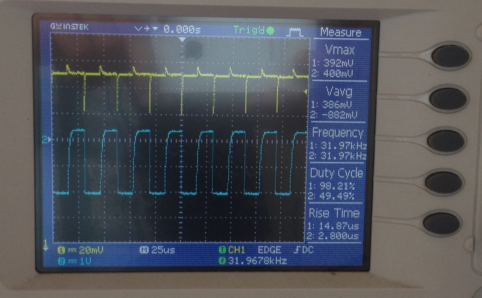
we tried to capture SCL and SDA(in while loop) from the ports on CC2541with out any slave connected(attaching the same for your reference). But with the slave connected, we are not able to recieve any acknowledgement from the slave after start condition.
please refer to the I2C code that we have implemented for our slave Gyro and let me know if any corrections to be done for establishing basic I2C communication link.
im also attaching the code for your reference
#include<ioCC2541.h>
#define BV(n) (1 << (n))
typedef unsigned char u8_t; typedef unsigned short int u16_t; typedef short int i16_t; typedef signed char i8_t;
My "uint8 HalI2CWrite(uint8 len, uint8 *pBuf)" function had a "I2C_STOP();" function at the end which sort of resets the communication after every write operation even though you are writing to just read from that register afterwards. This sort of resets the auto incrementer change in the chip and returns the registers from 0th register down in the consequent read operation.
To solve the problem, you can either have a parameter that decides when the "I2C_STOP();" command runs. Or you can make a new function for HalI2CWrite without the "I2C_STOP();" at the end. Use this new function only when you want to read from a specific register.