This thread has been locked.

If you have a related question, please click the "Ask a related question" button in the top right corner. The newly created question will be automatically linked to this question.

UART PARITY ERROR with sleep mode

Other Parts Discussed in Thread: CC2541

Hi

I am using TI BLE CC2541 chip. I am using CC2451 UART0 for transmission on UART.  UART configuration are as 2400 baud rate , even parity , one stop bit.

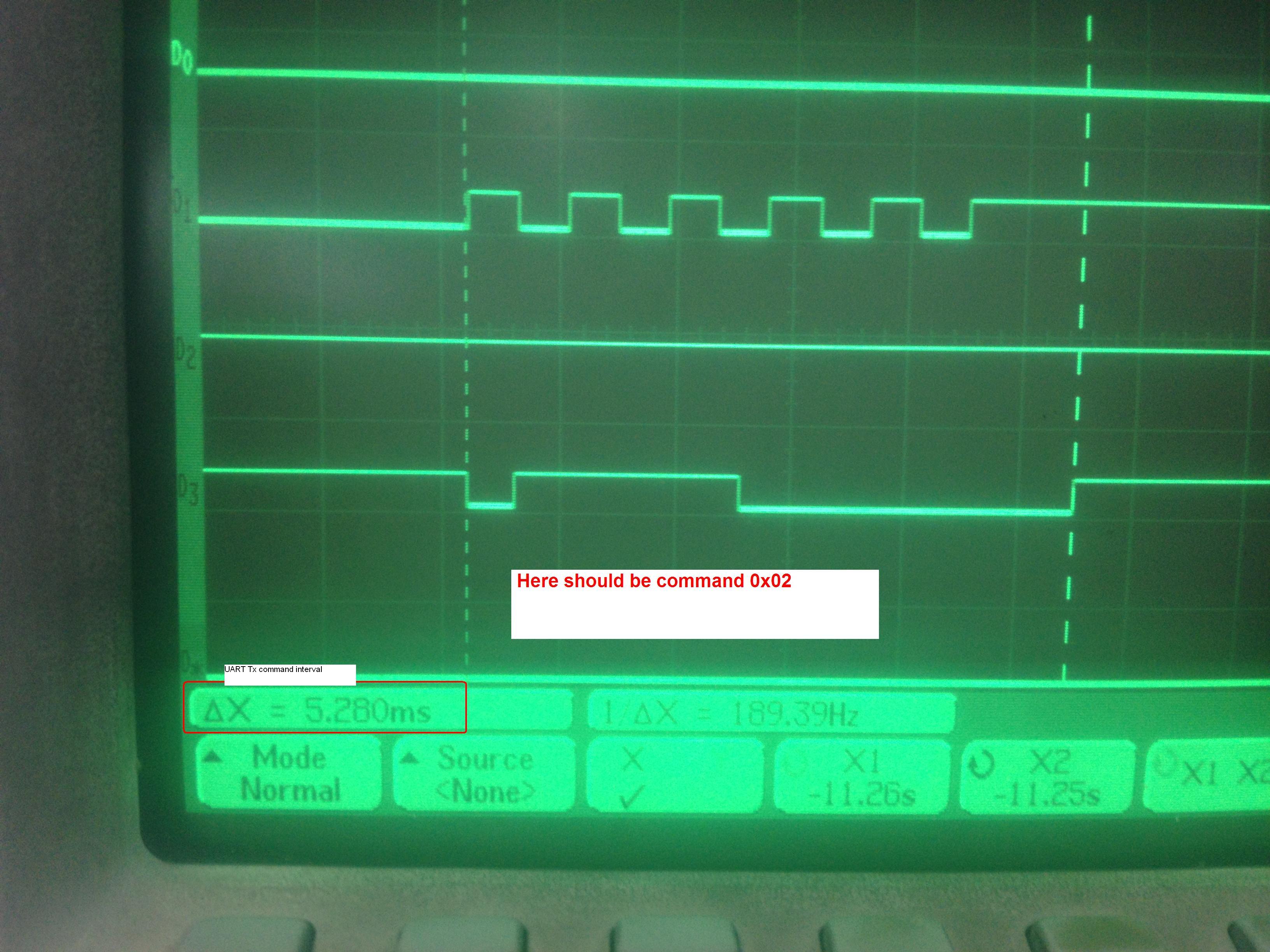
Some times during command transmission on UART, if i send 0x02 on UART buffer U0DBUF  then on other side means on my serial terminal it show 0x06 command rather than 0x02 command. From my Oscilloscope I found that command clock is stretching in transmission. Normally, for one command( 11 bits = 1 start bit + 8 data bits + 1 parity bit + 1 stop bit ) transmission it takes 4.54ms. But sometimes it takes 5.28ms and I get wrong command at other side.

Please provide me some help on this why this is happens?

Thanks in advance,

Dhvani Patel

  • Hi Dhvani,

    Could you paste in a minimal example of how to reproduce the issue? Setup, method for transmission, call to transmission etc. and I will try to reproduce it.

    Best regards,
    Aslak 

  • Hi Aslak,

    In my application , I am running TI CC2541 as slave (Peripheral ) device in power saving mode with PAIRING and Bonding is enable. When my slave device is completely bounded with master device and then i am sending 0x02 command. Before putting command on UART UODBUF , we set  one IO pin to low for 40 ms and then we put data on U0DBUF , after that we keep IO pin to low for 12 ms.

      Please find here code which we are using for command transmission

    #define SEND_IDLE    0
    #define START_DELAY  1
    #define SEND         2
    #define STOP_DELAY   3
    
    uint8 Buffer[128];
    uint8 Tail=0;
    volatile uint8 Head=0;
    uint8 Delay = 0;    // in turms of ms
    volatile uint8 flag = false;
    volatile uint8 State = UART_SEND_IDLE;  // uart tx state flag
    
    
    // an app function to write command in buffer for transmitt and exit
    
    uint8 writeUARTCmd( uint8 cmd )
    {
      Buffer[Tail] = cmd;
      
      if (Tail >= 128)
      {
        Tail = 0;
      }
      else
      {
        Tail++;
      }
    
      if(flag == false )   // if command on uart not seding set intr.
      {
        IEN2 |= UTX0IE;
      }
      osal_pwrmgr_task_state(TaskID, PWRMGR_HOLD);
      return SUCCESS;
    }
    
    
    // function set timer3 for delay.
    void timer3(uint16 msdelay)
    {
      Delay = msdelay;
      start timer3 for msdelay.
    }
    
    
    // UART0 tx ISR .
    // First check is any data to send on UART  by checking Head and Tail
    // If no data to send then disable UART tx intrrupt and set power in converse state.
    // If there is data to send on UART 
    // clear IF,  start TIMER 3 to 40 ms delay before actully data to put on UART U0DBUF register.
    // Exit.
    
    HAL_ISR_FUNCTION( halUART0TxIsr, UTX0_VECTOR )
    {
      if(Head == Tail)
      {
        IEN2 &= ~UTX0IE; 
        osal_pwrmgr_task_state(TaskID, PWRMGR_CONSERVE);
      }
    
      else
      {
        if(flag == false )
        {
          flag = true;
          UTX0IF = 0;
          if(State == UART_SEND_IDLE )  // check UART state IDLE
          {
            State = UART_START_DELAY;  // state change to START_DELAY
            timer3(40); // Start timer3 for delay
          }
        }
      }
    }


    // Timer 3 ISR is called every 1ms second
    // Decrement Delay counter 
    // if Delay counter is zero.
    // if UART state is UART_START_DELAY then call UARTSendCmd()
    // else if state is UART_STOP_DELAY  then call UARTSendComplete()
    HAL_ISR_FUNCTION( halTimer3Isr, T3_VECTOR )
    {
      TIMIF &=  0xFE ;        // cler timer3 flag;
      T3CTL &= ~0x10;          //stop timer
      Delay--;
      if(Delay <= 0) {
        T3CTL |= 0x04;
        if(State == UART_START_DELAY ) {
          UARTSendCmd();
        }
        else if (State == UART_STOP_DELAY) {
          UARTSendComplete();
        }
    
      }
      else {
        T3CTL |= 0x10;       // start timer
      }
    }
    
    
    // Function put Data on UODBIF from local Buffer 
    // And start timer3 for 12ms delay 
    // Put state to UART_SEND
    void UARTSendCmd()
    {
      
      UTX0IF = 0;
      U0DBUF = txBuffer[uartTxHead];
      IEN2 &= ~UTX0IE;  
      State = UART_SEND;
      timer3(12);
    }
    
    
    // after 12ms delay
    // set UART state to idle
    // Enable UART tx interrupt and set interrupt flag true 
    // So UART tx interrupt called again. 
    void UARTSendComplete()
    {
      Head++;
      if(Head >= 128)
      {
        Head = 0;
      }
      State = UART_SEND_IDLE;
      flag = false;
      IEN2 |= UTX0IE;
      UTX0IF = 1;
    }
    

    Thanks in Advance

    Dhvani Patel

  • Hi,

    What is the setup code that you use for the uart?

    What's what on the scope picture?

    Best regards,
    Aslak 

  • Hi Aslak,

    For reproduce this issue, you have to set up UART with 2400 baud rate , event parity , one stop bit. Now send  number commands on UART when paring and bounding complete callback call. and also send number of command on uart  when some event comes to slave from master , like proximately, unread, and some other .. . This issue is not reproducing every time. Its comes randomly.

    Please look in above sample code for transmission and if i am missing something. Please provide your suggestion.

    Thanks

    Dhvani Patel

  • Hi,

    Sorry that I was not specific. I would like to see your exact setup code to be able to reproduce it exactly, to see if there is something wrong with the setup, and to see which pins etc you are using. 

    Where does the clock signal on the oscilloscope picture come from?

    Best regards,
    Aslak 

  • Hi Aslak

    Here is my UART setup.

    P1.4 -> Rx
    p1.5 -> Tx

    No Hardware flow control.

    UART  setup:


    PERCFG |= 0x01;                                                                                     // UART0 Alt.2
    P1SEL  |= 0x30;                                                                                        // Enable Tx and Rx on P1.
    ADCCFG &= ~0x30;                                                                                 // Make sure ADC doesnt use this.
    U0CSR = CSR_MODE;                                                                           // Mode is UART Mode.
    U0UCR = UCR_FLUSH ;                                                                        // Flush
    U0BAUD = 59;                                                                                           // For 2400 baud rate
    U0GCR = 6;                                                                                               // For 2400 baud rate
    U0UCR =  UCR_D9 | UCR_BIT9 | UCR_PARITY | UCR_STOP;    // EVEN PARITY BIT , 9 bit transfer,  parity enable , High stop bit.
    URX0IE = 1;                                                                                               // Set Receive Interrupt Enable Bit
    UTX0IF = 1;                                                                                                // Set Transmit Interrupt Flag Bit
    U0CSR = (CSR_MODE | CSR_RE);                                                    // UART mode with Receiver enable

    In waveform 2nd wave show a TX wave with transmission delay about 5.28ms.

    Regards,

    Dhvani Patel

  • Hi

    Please anyone can suggest me above configuration if i am wrong and provide me some input as i need its urgent.  ?

    Thanks in Advanced,

    Dhvani Patel

  • Hi Dhvani,

    So I'm not really able to reproduce the error. Can you try to make the error occur outside of an active connection? I mean, to send a lot of packets when not advertising, not in a connection etc, and see if that ever fails. Just to isolate the problem a bit.

    Aslak

  • There is a H/W bug in the UART module such that it sends 2 stop bits when configured to send 1.

    So, can you configure your receiver to accept 2 stop bits?


  • Hi Aslak,

    Thank you for looking in this issue.

    This clock stretching problem occurs when my slave device is  in Advertising  mode  or in Pairing mode or in  connected mode with master and receive alerts from master . 

    In a simple test, in which i am sending lots of commands on UART without Advertising , then its work fine.Please can you suggest me that this problem occurred due to some activity on RF ? And provide me some possible solution with same UART configuration. Waiting for your response .


    Regards,

    Dhvani Patel

  • Hi Harry,

    Thanks for your suggestion.

    If this is H/W bug in UART module then every time there is a parity error comes. But in my case,clock stretching issue comes inconsistent and it is occurred  when my slave device is  in active mode means in Advertising mode or in Pairing mode or in Connected mode with slave device and master sends some alert to slave.

    Regards

    Dhvani Patel

  • Hi Aslak,

    Please find here image which show that command bit stretched during transmission when my slave device CC2541(peripheral)  is connected  with master device(Central).

    Please provide me some solution. Is this a bug from TI or a valid scenario ?

    Regards,

    Dhvani Patel

  • First of all, we should stop talking about "clock stretching" because there is no such thing wrt UART - clock stretching is a term/technique from I2C. In UART, there is clock drift (which we know is within 6ppm) and clock error - which is shown to be 0.14% for 2400 baud in the User's Guide.

    I suspect that the 2 stop bits bug persists when parity is used, although it looks like it manifests differently. If so, then there are 12 bits expected per byte: 1 start, 8 data, 1 parity, 1 stop, 1 erroneous bit and therefore 12/2400 -> 5 msec per UART frame.

    What I see in the screen shot above is data byte 0xC1 sent with ODD parity and the erroneous bit is not an erroneous 2nd stop bit but an erroneous 2nd parity bit.

    There is absolutely no way that radio activity is affecting the digital domain (e.g. baud clock and UART shift register operation).

    If I get time, I will try to scope the setup myself.


  • I scoped the setup and everything looks fine, as expected. And the 2 stop bits bug is still a 2 stop bits bug even when parity is used (i.e. there are always 2 stop bits after the parity bit and there is never 2 parity bits).

    So, I looked some more at the hal_sleep code and I realized that what you are capturing on your scope is the transition into sleep while the byte is still shifting out.

    The first step of going to sleep is to switch from the 32-MHz clock to the 16-MHz clock. And so in your capture above, while the byte is shifting out, the transition to the 16-MHz clock happens exactly on the 7th (of 8) data bit, and thus the effective baud rate is suddenly 1200 baud and all bits are shifting out twice as long. In the capture above, the parity bit is missing, probably because PM is entered and the UART sets Tx to high impedence.

    So - you must disallow PM until your UART traffic is finished, Mr. Patel ... perhaps re-allow PM by the UART Tx done ISR (or a flag or event set by it)?


  • Hi Harry,

    I have tested this same things with disable POWER_SAVING macro and I am getting same result. 1) Sends lots of command  on UART when my device not in advertising any packet , I am  not getting any wrong command on UART receiver side. 2)   Sends lots of command  on UART when my device in Advertising mode , i am getting some wrong commands on other side of  UART  receiver.

    Please you can try this simple test. Send 150 number of command in idle condition and in Advertising  mode.