This thread has been locked.

If you have a related question, please click the "Ask a related question" button in the top right corner. The newly created question will be automatically linked to this question.

CC2540 connection problem

Other Parts Discussed in Thread: CC2540

Hi,

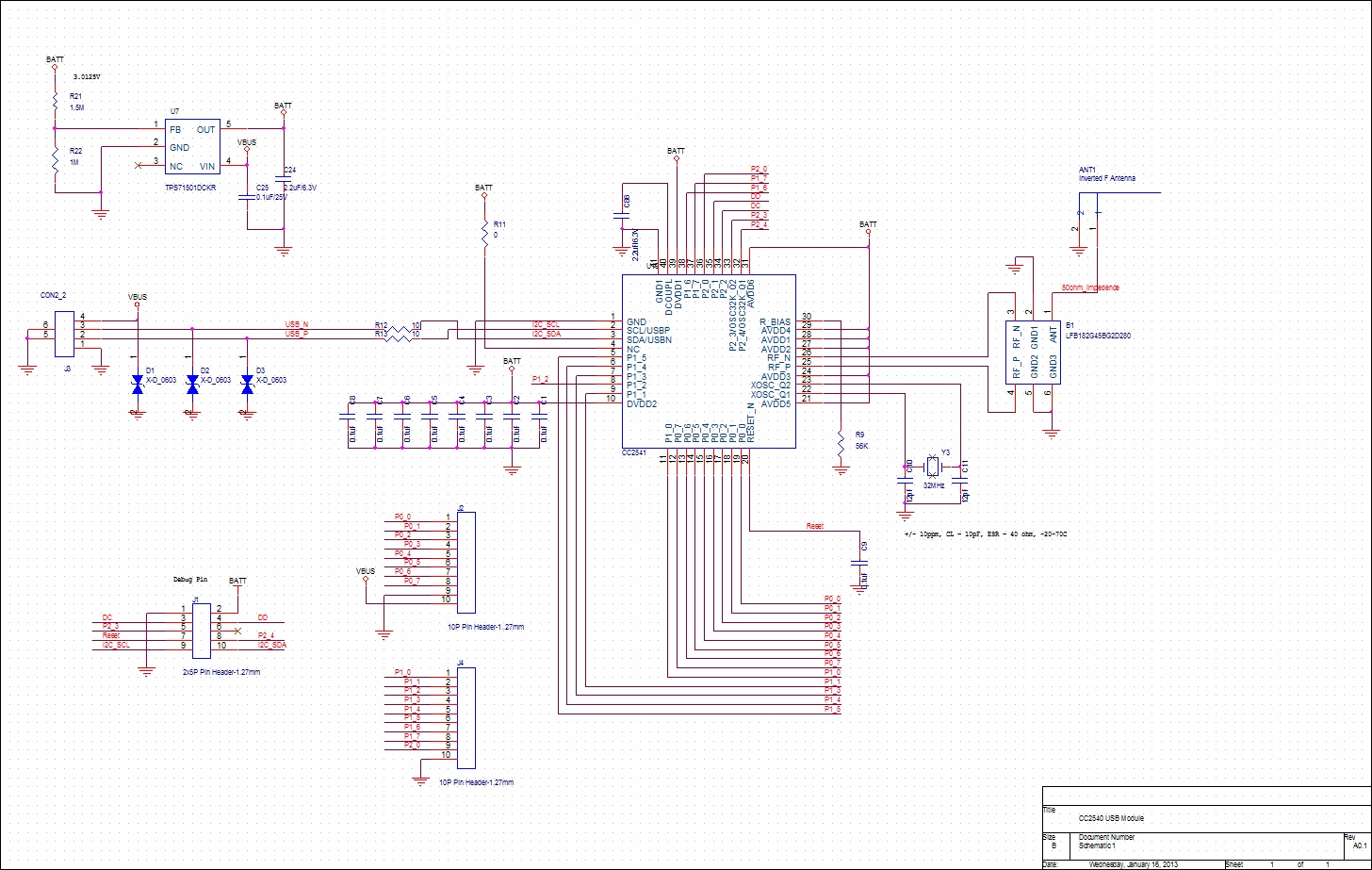
Currently we are working on a project using CC2540 as a USB dongle to connect to a PC to receive UART data from a device thru wireless BLE. However we encounter a problem when verifying the design.

We use the keyfob application program on a iPhone 4S/iPad Mini trying to connect to our custom made CC2540 USB dongle. When pressing scan key on the iPhone app, it will sometimes successfully discover device and show the "disconnect" button. However, most of the time the app will remain in the "connecting" stage.

It seems to me that it might be problem with RF antenna as I can successfully program and erase CC2540 using the CC debugger tool. So I assume that hardware on the digital side is ok.

I implemented the inverted F antenna as application note AN043 suggested. I've also attached my schematic and gerber. Any suggestion on how I can verify and confirm that it's an antenna problem will be welcome. Also please do help comment on my layout as this is my first time designing a RF board.

  • Hi Steve,

    Do you use TI BLE MultiTool iOS App or do you have your own? If you could capture the communication with the TI Sniffer, It might be easier to identify the issue. Do you have an CC2540USB Dongle to use as a sniffer? Guide here.

    I'll let someone more hardware oriented answer to the questions related to the PCB/antenna design.

    Best Regards

  • Hi Steve,

    Can you verify this with for example the TI BLE SensorTag app on the appstore?

    Can you connect to the device using for example BTool or Device Monitor?

    Best regards,
    Aslak 

  • Steve,

    From an RF standpoint, the layout looks okay (at least what I could see in the picture).

    The end of the antenna that you point out needs to be connected to the ground plane. Also, there should be a solid ground plane under the RF, which you do maintain in layer 3.

    The Layout Review Technique app note (http://www.ti.com/litv/pdf/swra367a) has a ton of good info on considerations for RF layout.

  • Hi Nick,

    Thank you very much for your quick response. We are using the TI BLE MultiTool iOS APP. I will try to capture the communication with the TI Sniffer. Thanks for the tip!

    BR,

    Steve Chen

  • Hi Aslak,

    We will first work with the sniffer using the TI USB dongle since that the only EVM kit we have. I will sniff the BLE connection status with BTool using the dongle as well. I will post my result later tonight. Thanks for your tips!

  • Hi Nick and Aslak,

    I used both TI sniffer with TI USB dongle and BLE Multitool app with iPHONE4S.

    When using the BLE Multitool app (version 2.1), I was able to connect to our custom BLE USB dongle with RSSI of -43dBM to -96dBM depending on distance.

    However, when I used the TI Keyfob source code (V1.2.1) to build my custom iPhone app, I was not able to connect to our custom USB dongle with RSSI over -72dBM.

    Moreover, when I sniff during the connection of my iPhone to our custom USB dongle, I see that there is error at FCS field. I've attached the log from BLE sniffer. Any suggestion on pointing to where the problem is will be greatly appreciated!


    7367.ble-log-20130117-2030.psd

  • Hi Steve,

    Can you clarify what you mean? Do you see worse performance with one iOS app compared with another?

    FCS errors do occur from time to time for whatever RF reason. There is a bug when loading .psd files, so I can't see your RSSI values. However, you can see that for instance packet 4602 was correctly received by the iPhone (NESN=SN+1, i.e. the next SN is what the previous Next Expected SN was), even though the sniffer had an error receiving this.

    Best regards,
    Aslak 

  • Hi Aslak,

    Not sure if its worse. But this is what I have done,

    I've load two different TI app to my iphone

    1) TI BLE Multitool app (I download from apple app store)

    2) TI BLE Keyfob app (download from TI website)

    Connecting to the same custom BLE USB dongle, I moved my phone to a distant about where the RSSI read back -76dBM (I got this number using the Multitool app). Then I try to connect to the USB dongle using two different app.

    1) TI BLE Multitool app will show "connected" state in the Profile menu

    2) Hitting the "Scan" key on the Keyfob app, it will change from scanning to connecting state, but it will remain in the connecting state despite my effort to move the phone closer to the dongle. However, if the phone was close to the dongle from the beginning I was able to see the "disconnect" state (I assume that device profile is properly received)

    I just wanted to know that if this could be caused by hardware problem or it is more firmware/software oriented problem. The two different app, do they go thru the same connecting process?

    BR,

    Steve Chen

  • Hi Steve,

    It may say connected, but can it discover services and characteristics? I.e. is it actually connected and able to do something useful?

    It sounds impossible that two different apps actually have different RF performance, so I think it's just a difference in how they report the state.

    Best regards,
    Aslak 

  • Hi Aslak,

    Using the Multitool, it was able to discover service and characteristics under the profile tab.

    I feel the same way that its impossible for the app to change the RF performance. I will look into the code. But just out of curiosity, does TI release source code for the Multitool?


    BR,


    Steve Chen

  • Hi Steve,

    We will release (and had released) a sensortag app example, which is similar to the Sensortag app and the Multitool app. However, it is temporarily down while we wrangle with the legal department about app distribution and license agreements.

    Best regards,
    Aslak 

  • Hi Chatto,

    After spending some time to read and understand the application note AN098 and AN068, I have a question. What's the impedence needed on the differential pair of RF signal to the balanced port of the Murata Balun? The reason I ask this is that I have the change the stack height (to 1mm) of my pcb board due to mechanical constrains.

    BR,

    Steve

  • The differential pair of RF signal to the balanced port of the Murata Balun is matched to the output impedance of the chip stated in the CC2540 datasheet.

    Using a chip balun gives you a distinct advantage in your case, it is not as susceptible to layer stacking height as a discrete balun would be. I would recommend having provisions for a shunt component across the balanced inputs of the balun. You should be okay with the chip balun being symmetrical and close to the RF pins of the CC2540.

  • Hi Chatto,


    Problemed solved! It turns out that I didnt solder the Balun well so that there are so interference with the RF. The custom boards I got back from the SMT factory worked well!! Thanks for everyone's help in this post!


    BR,


    Steve Chen

  • Hi,

    where is the Pi RF network between the balun and antenna? 

    Without that , the antenna and the wire to it may  not be Caliban to 50 ohm and you may have a TX/RX problem. 

    -Nissim

  • When using a chip balun, the Pi or T filter/matching network is integrated into the chip balun. The unbalanced output impedance of the chip balun is 50 ohms.

    However, it is good practice to have a shunt and series element at the antenna feed point to ensure that if there is some impedance mismatch at the antenna feed point, one can match using the passives.

  • Hi Nissim,

    Thanks for the reply! I am no RF expert. But from the application note I read, it says that the Balun does not need a Pi network.

    BR,

    Steve