This thread has been locked.

If you have a related question, please click the "Ask a related question" button in the top right corner. The newly created question will be automatically linked to this question.

2.4G Meandering F Ant Differences

Other Parts Discussed in Thread: CC2511, CC2540

I looked around and didn't see this addressed.  Apologize if I'm missing somthing totally obvious here..

I'm looking to replicate a trace antenna for use with a CC2540.  I see what appears to be the same meandering F antenna in different designs: AN043, CC2511 USB dongle, CC2540 USB dongle, CC2540 key fob, CC-ANTENNA-DK #15, I'm sure there are more.  The issue is all of these different examples appear to be slightly different from each other. 

In AN043 the ground plane extends out past the L1 segment (by D3), on the 2540 key fob gerbers the ground plane stops short of the L1 segment, on the 2511 dongle gerbers the ground plane stops directly in the middle of the L1 segment.  Looking at the CC2540 dongle the ground plane extends past the L1 segment (I couldn't find the gerbers but I didn't look very hard) so this may be the D3 in AN043, on the CC-ANTENNA-DK #15 antenna the ground plane extends way past the L1 segment (this is obviously much larger than the D3 value indicated in the AN043 app note.

I would jump to the conclusion that even though these antennas all look alike that they are not the same design however the CC-ANTENNA-DK #15, specifically references AN043 and what I see in AN043 and what's on the board are different in not only with the above mentioned ground plane difference but the CC-ANTENNA-DK #15 has copper on both sides  of the board for the antenna trace and the two copper traces are stitched together with vias.  The CC-ANTENNA-DK also has the last part of the L1 segment turned parallel to the ground plane.

I'm further confused with the references I've read on this blog about shortening the length of L1 to tune the antenna to different substrate thicknesses (which for the AN043 antenna would increase or decrease the distance between the end of the L1 segment and the ground plane.  Should I assume that the tuning is both changing the length of the meander AND changing the distance between the end of the L1 segment and the ground plane?  If the latter is the case then I would assume different effects in trimming the L1 segment in the AN043 designed antenna and the CC-ANTENNA-DK.

What am I missing here?

  • Bryan,

    One way to answer your questions is to EM simulate the various inverted F antenna (IFA) artworks and compare the s-parameters.  Sonnet SW distributes "Sonnet Lite" free of charge and it's easy to learn and use.  I also recommend MWO Axiem and Agilent ADS Momentum -- all will easily simulate the IFA's.

    Also, have you considered using a COTS antenna?  They will be smaller if a higher dielectric substrate is used.  However, I don't know how cost sensitive your project is.

    Regards,

    Eric Hooker

  • Hi Eric,

    Thanks for the response.  Guess I'm more looking for an answer about the reasons for the differences across the ground plane implementations of what appear to be the same antenna in TI literature and dev kits.  If the dev kits and literature were consistent I'd wouldn't be asking the question.  Was hoping not to have to get into this up to my waste to throw down a simple design that would work pretty close to app note implementation/characterization.  Thanks for the software suggestion and the the s parameter recommendation to start the research.    I'll start the self education process.

    Bryan

  • Hi Bryan,

    For the antenna itself follow the exact dimensions in AN043. Try to place the antenna such that it do not have ground plane on either sides (except underneath). Add at least 2 components close to the antenna which can be used for antenna tuning. If possible also plan at least one board spin to allow antenna tuning by shortening the antenna length.

    Factors such as ground plane size and shape, plastic housing, PCB thickness, etc. etc. will change the antenna impedance so it will always be necessary to tune the antenna on prototypes for best performance.


    Best regards,

    Fredrik

  • Hi Fredrick,

    Thanks for the response.

    So the real answer to my question, and I’m pretty sure I and my coworkers already knew this, is that ‘it’s not as easy as just throwing down an app note design’ when it comes to rf.

    The implication here being that any antenna design is necessarily an iterative process started off by a ‘best guess’ (although a best guess in this case is an app note or a simulation) and then refined to a specific application.

    If in effect this is the answer to my question (in your opinion) then you have answered my question.  Then just a quick reply and I'll hit the green button and close this thread down.

    Thanks again,

    Bryan

  • Hi Bryan,

    I thought I would comment again on your thread.  You can predict the IFA (antenna) performance with reasonable accuracy with an EM simulator but it will take some time to get up to speed with the tool.  You may also predict the influence of nearby traces, planes, the plastic housing, etc if you have the time.  Fredrick's suggestion to include antenna matching parts and/or plan for an extra pass is also very good advice.  Of course, you need to have some idea of the IFA impedance variations to determine a proper antenna matching topology.  

    My previous comments on considering a COTS solution may also be useful to you.  You could experiment with a COTS antenna to determine how ground planes, a plastic housing, etc influence it before committing to a PCB layout. This may save you one PCB layout pass.  If you search websites like Digi-Key you will find COTS 2.4 GHz antenna solutions.  Of course, a COTS antenna may cost $2 to $4 in quantity so this option may not work for you depending on your required BOM cost goal.

    Regards,

    Eric Hooker

    RF Consultant 

  • Hi Eric,

    Thanks for the further comment.  We're trying to get around using a whip(ducky) antenna if at all possible and it seems like you're going to suffer similar demons (as to trace antenna's) even with a cots chip antenna. I might be making this harder than it needs to be but it seems like whether you start with a reference, come up with your own design, or use a chip antenna, in the end (and along the way) you're going to need access to and know how to drive a network analyzer to do anything otherwise you're pretty much blindly groping when going through the tuning exercise.

    Bryan

  • Hi Bryan,

    I wasn't proposing a whip antenna but yes a chip antenna is what I meant for you guys.  Also, yes you need a network analyzer to work with 2.4 GHz wireless devices otherwise you're in the dark as you mentioned.

    If you want to quickly learn how to do this work (design an antenna, design antenna matching networks, "drive" a network analyzer, etc) then I could help you.  I've mentored many engineers over my career.

    Regards,

    Eric Hooker

    RF Consultant

  • Hi Eric,

    Thanks for the mentoring offer.  This is not necessarily on my critical path right now.  I just took a slight deviation off my current path on the off chance that asking the question might yield an easier answer than simulation (or ref design), implement, test, tweak, re implement, test, final tweak.  I wasn't necessarily expecting the easy answer but I wanted someone who knows more than me to put it down in words.  You and Fredrick have done that.  Thanks.

    I've downloaded sonnet and I will try to find some time to go through the tutorials and play with the s/w.  But for now I'm going to go with the ref design jumping off point and worry about the implement, etc if I need to.  We have someone else at my org working on this stuff right now.  He's much further along than me but not at the point of antenna geometry modelling and simulation.   He's using a network analyzer for matching right now but my gut tells me that without a good starting point matching doesn't mean a whole lot.  In other words, no matter how hard you wish and or try for it not to be some things are inevitable.

    Thanks again for the offer and the good words.

    Bryan

  • All,

    Here is a link to a useful YouTube video on the inverted-F antenna. 

    http://www.youtube.com/watch?feature=player_embedded&v=KUMda5WOojU#!

    Eric

  • All,

    The IFA described in in AN043 was analyzed with Sonnet Lite EM software.  This SW is provided free of charge from Sonnet. 

    A 3D view of the IFA analyzed is shown below:

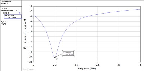
    The predicted S11 response is next.  The best S11 was at 2.2 GHz rather than the desired 2.45 GHz.  This could be due to many factors such as the exact location of the shunt trace ground via, Sonnet box size, cover distances, thickness of air layers above and below PCB (FR4) layer, etc.  I'm not certain exactly how the EM simulation shown in AN043 was setup.

    Sonnet generates S-parameter data after the simulation is complete and saves to a file if desired.  The predicted S-parameter data can easily be matched at 2.45 GHz with lumped components.  Sonnet provides a text editor so ideal components can be simulated along with the predicted S-parameter data.  Below I show the schematic simulated in Sonnet.  I used Agilent ADS to show the schematic view for clarity.  Notice I added a series 1.2 pF cap and a shunt 0.4 pF from the 50 ohm point.  The "S1P" data box uses the EM generated S-parameter data.  A better simulation would include ESL and ESR for the caps. 

    The new S11 plot (antenna matching network + EM simulated IFA) is shown below.  Notice the best S11 dip is now at 2.45 GHz. 

    I was not able to attach the Sonnet EM (*.son) file.  Contact me via email if the file is desired or there are any other questions.  Thanks to Jim Merrill at Sonnet SW for his technical support.

    Regards,

    Eric Hooker

    RF Consulting Engineer

  • Hi Eric,

    Many thanks for the utube pointer and the simulation.  Haven't had time yet other than to just scan through both but I can't see how either would be anything less than helpful.

    Questions on your sonnet simulation of the AN043 antenna.

    The 3d view.  It's not clear to me exactly what I'm seeing.  Is it that the drive point is on the bottom of the board (the apparent vertical between the IFA and the green rectangle)?  Are you indicating that the ground plane is on the bottom of the board and the IFA is on the top?  What is the little angled square between the two verticals (adjacent to the green rectcangle).

    What thickness board did you assume in your test.  The AN043 references the CC2511 dongle design.  If you look at the readme associated with the gerber zip they indicate what appears to me to be a non standard thickness of FR4.  What's also interesting is we have a CC2540 dongle and the board thickness is 0.062.  Posts I've seen on this forum indicate that dielectric thickness must be accounted for in antenna tuning.

    The difference between matched and unmatched appears to be night and day.  It looks like the unmatched would virtually not work at all S11 is so high at 2.45G. 

    Did you try to tune the IFA you simulated prior to matching it?  Seems to me that if you can move the resonance as close as possible to 2.45G prior to matching the better performance you'd get from the antenna.  Would be interesting to see the simulated differences of a 'as is' matched (the simulation you posted) and the 'as is tuned' then matched.

    Thanks again,

    Bryan

  • Bryan,

    I'm on travel now and this reply is from my phone so my answers will be short. 

    The 3D view shows the IFA on layer 1 and the ground rectangle on layer 2. You can also see the shunt line gnd via and the via port connected to the 50 ohm feed line. 

    I used a PCB thickness of 1 mm per the readme text file from TI.  The PCB is actually 4 layers thick but Sonnet Lite only allows 2 metal layers. Sonnet Pro was used to simulate the IFA with the gnd rectangle on layer 2 but with a layer thickness of 0.25 mm. Then the entire PCB thickness was set to 1mm. This was found not to make much of a difference to the resonant freq. 

    The IFA freq can be increased by decreasing the overall length per Sonnet. 

    Even if the IFA was resonant at 2.2GHz, it could still be used at 2.45 GHz ISM band if matched up. 

    Eric Hooker

  • Hi Eric,

    Thanks for the response.  Regarding the 2.2G resonance and matching.  I think what you're implying is that the matching/network antenna combo become the resonant circuit?  Lot's of good info for when I'm on the critical path and need to pick this kind of stuff up.

    Bryan

  • Bryan,

    Yes, that is correct -- the matching network and IFA make up the antenna. 

    BTW, Sonnet requires the circuit to be placed in a 6 sided metal box. But, I set the box base and cover to "free space".  Only the base and cover can be not metal i believe. Your  product will probably be inside a plastic case which will influence the resonant freq.  Also, I set the box size much larger than the IFA size so not to influence the response.  This can all be modified and then resimulated.  As you can see, there are many variables when running an EM sim. 

    Regards,

    Eric Hooker

  • Hi Eric,

    Many variables means many assumptions.  There's where I see the rub with simulations in general.  The simulations will get you into the ball park but reality has this way of always sneaking up and biting theory in the butt, both because of assumptions (known knowns) which are inaccurate,  factors assumed to be second or third order factors (known unknows) that really aren't, and factors one doesn't know need to be considered (unknown unknowns) .  So GIGO as they say.

    Thanks for all the followups. I'm going to hope I don't get put on this critical path because it starts to sound like a not so easy learning curve.  Would probably need to punt if I need to get below 100ft anyway.

    Forgive my waxing rumfeldian. 

    Bryan

  • Hi Eric,

    Another question about matching.  Would it be correct to say the part of the energy circulating in the matching network is not radiating out the antenna?  Is this why people say 'you can match to a rock but that doesn't make it a good antenna'?   This would be like connecting where your antenna would be to ground (or leaving it open) and making the matching network resonate at you desired frequency of operation?  This would imply that the closer your antenna is to resonance before matching the better antenna you will have because more of the power is being radiated and less is being lost in the matching network?  Match implies no power reflected back into the transmitter right? Just trying to wrap my head around this stuff from a seat of the pant point of view.

    Thanks

    Bryan

  • Bryan,

    EM simulations are very accurate if the simulation file is setup correctly.  Compare measured versus EM simulated s-parameter plots for micro-strip or strip-line filters or antenna published in the literature.  The simulated versus measured plots are nearly identical except perhaps at the attenuation extremes in the case of filters.

    One of the assumptions I made was to simulate the AN043 MFIA in free space for example.  (TI gave very few details on their EM simulation.)  Usually the PCB will be housed inside a plastic case which needs to be taken into consideration.  Its not a GIGO issue -- it's a what are the required conditions for the EM simulation issue.

    Yes, RF & microwave design is not learned overnight.  But, if you are persistent then you will learn it.  I've been working at RF/microwave for 20+ years and I'm still learning new things.  :)

    Eric Hooker

    RF Consultant

  • Bryan,

    I just noticed your questions concerning matching networks.  Yes, the goal is to reduce reflections for maximum power transfer.  Remember the fun all of us had in Electromagnetics class?  Matching is getting back power otherwise lost to reflections.

    Yes, it's better to have the antenna matched at 2.45 GHz without any L-C matching required.  One could use a knife and shorten the antenna line length to move the resonance up if the best S11 was at 2.2 GHz as Sonnet predicted.  Or, it could be tuned up slightly as I showed with a matching network.  The overall antenna gain will be slightly worse with the matching network.  You have to determine if that's okay for your application (link analysis) -- my guess is yes.

    Regards,

    Eric Hooker

  • Hi Eric,

    Thanks for continuing on with this.

    I get your point about 'good enough' ie a miniorloss associated with the matching network will probably be minor with respect to overall radio operation.  I guess my thought was that you're best off to start with an antenna that resonates as closely to your intended TX/RX freq.  Not necessarily that it has to be perfect because of all the other things that will affect it, but more that the closer you are to your desired operating frequency when you start the better off you will be when tolerances and other things that aren't easily controllable are put into the mix.

    So I agree, having to have your antenna absolutely optimized is one of those things that's nice to have but in the end the 80/20 rule applies, i.e. if you have all the time and money in the world you'll eventually get there, but in almost every case you do not.

    Now with the antenna design and matching arm waved as far as we can probably go, i.e. I think the real problem we've been trying to solve with antenna design and matching is the deep nulls we experience when operating in an indoor environment.  I'm not sure this problem can necessarily be meaningfully addressed with just antenna design and matching.

    I don't want to make the assumption that diversity is the only solution to the the null problem.  There may be other ways to attack the nulls without adding the extra complexity in s/w and hardware.   No one wants to add the expense and effort to implement diversity but ironically we've spent so much time mucking around with antenna's and matching that I think we've already spent the time and the effort, only to have to now spend the time and effort on diversity.  My coworker who's doing the primary antenna design and matching efforts indicated diversity right out of the shoot as the solution to the nulls.  It made very good sense to me at the time and I was gung ho to go there but my lack of even an armwaving understanding about the antenna's and matching kept me from being able to lobby on behalf of diversity.


    So can we solve our null problems with antenna's and matching optimization?  Do we need to move on and focus on something else?  Is diversity the next tree we should be barking up?  You've had good suggestions and considerate explanations so far.  Any thoughts?

    Thanks again,

    Bryan

  • Bryan,

    What is the "use case" for your product?  You mentioned an "indoor environment" but provided no more details.  What range do you require and what type of indoor environment do you need to work with?  (Size of rooms, number of floors, construction type, etc.)  If you prefer not to discuss this on a public forum then send an email.  I could provide a bit of general guidance.

    Regards,

    Eric Hooker

    Consultant

    Eric Hooker RF Consulting, LLC

    EHooker-RF@msn.com

  • Hi. Eric,

    You never know when you're too close but not touching the secret sauce, at least this shouldn't be broadcast to the world.  So I'm sending you an email to answer your questions.  At the same time I find these forums very helpful when researching designs and solving problems so I'd like to jump back to this forum eventually.

    Bryan

  • All,

    I had additional time to study this antenna (MIFA) design.  I was curious what the radiation patterns would look like with a plastic case over the antenna.  I used Sonnet Pro EM software to do this work -- the Pro version allows calculation and viewing of the radiation patterns.

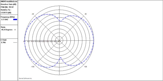
    The plot below is for the antenna in free space (XY plane).  Compare to figure 8 of AN043.  The plot is at 2.2 GHz rather than 2.45 GHz since this simulation had the best match (S11) at 2.2 GHz.  I understand that the edge of the PCB tunes the antenna slightly but i haven't simulated that case yet.  The radiation pattern at 2.45 GHz was not that much different even with the degraded S11.  As I wrote previously, a simple matching network "pulls" the antenna match to 2.45 GHz.

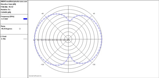
    The next plot was from a simulation with a 0.5 mm plastic case 2.5 mm above and below the antenna PCB.  The dielectric stack-up was then 2.5 mm of air, then 0.5 mm of plastic (Er=2.4) and then 65 mm of air above and below the PCB.  The plot looks nearly identical except the predicted gain increased slightly.  Both of these plots are relative to the max gain shown to the left of the plot. 

    If you have any issues using this antenna design notice there are angles where the gain drops 20 to 25 dB.  Both of these plots are set to 5 dB/div just as was done in AN043.  Your system design must accept these antenna gain nulls to be sucessful.

    Regards,

    Eric Hooker

    RF Consultant