This thread has been locked.

If you have a related question, please click the "Ask a related question" button in the top right corner. The newly created question will be automatically linked to this question.

PAN1323ETU module start up

Other Parts Discussed in Thread: MSP430BT5190

Hello all, 

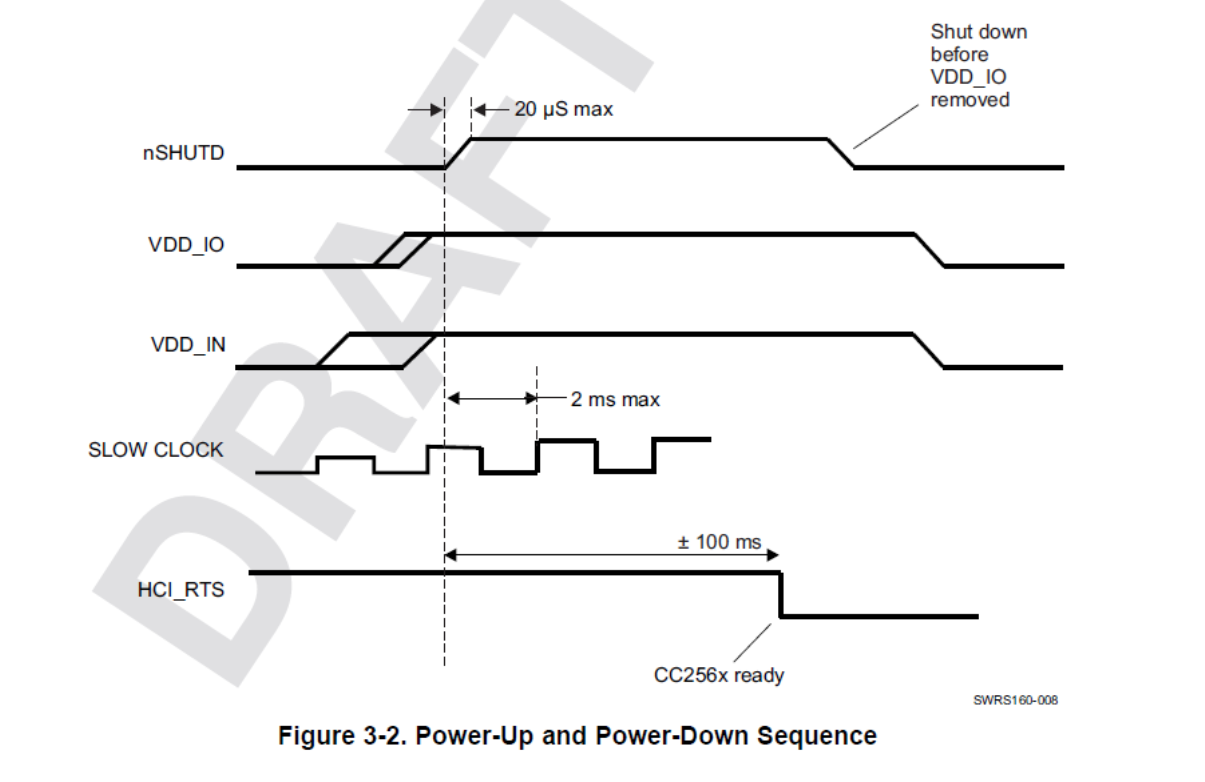
I have a PAN1323ETU module that I am trying to get working. The board is powered at 3.3V, with all logic to the module at the same voltage. (The board has level shifters for the CC256x.) I am supplying a 32.768 kHz slow clock, and I apply voltage to the nSHUT_DOWN pin after the clocks are stable. It takes around 10 seconds for the HCI_RTS line to go low. This sounds like the module is just timing out? It does not respond to any commands sent to it. Anyone have any ideas? 

Thanks,

JD

  • Still having a hard time with this. Anyone have any ideas?  I have even tried another module. When I scope the slow clock that I am generating from my uC, it is at 32.68kHz. Any reason why the RTS line would drop low so long after? Any pointers would be appreciated.

    Thanks,

    JD

  • Hi Jeremiah,

    Does the module work on one of our evaluation platforms: http://processors.wiki.ti.com/index.php/CC256x_EVM_Platform

    How are you generating the slow clock from the uC?

    The RTS line should go low within 100ms of asserting nSHUTD: http://processors.wiki.ti.com/index.php/CC256x_Testing_Guide


  • Hi Zahid,

    I do not have access to the TI eval platforms. I am using an Atmel 2560 uC and I use an 16-bit Timer/Counter with output compare module. I toggle the output pin and like I said I can see 32.68 Khz on the output.


    Thanks,

    JD

  • I am having similar issues with a PAN1326 module on a custom board.

    The module consistently requires 25 seconds before RTS goes low.

    No response to any commands sent. I have tried with CTS both high and low.

    If I send enough commands, RTS will eventually go high. E.g,. 254 HCI_Read_Local_Version_Information commands. Again, this behavior is consistent from one run to the next.

    I have the same symptoms after replacing the PAN1326 module.

  • Hi Steve,

    Could you please let us know what is the host processer you are using?

    How are you generating the slow clock from the uC?

    Could you provide us the kernel logs?

    Is it also possible to for you to capture the of the lines (as in the boot up sequence of the datasheet).

  • Hi Sundeep,

    Thanks for your reply.

    The host processor is MSP430BT5190 in 100-LQFP package.

    The slow clock is generated by a 32768 Hz crystal oscillator, SG3030JC:

      http://www.eea.epson.com/portal/pls/portal/docs/1/1629448.PDF

    This oscillator output is connected directly to the host's P7_0_XIN pin and then becomes ACLK. The on-processor oscillator is bypassed.

    I output ACLK on the P11_0_ACLK pin, which connects to the PAN1326's SLOW_CLK_IN via a level translator.

    I used a 16 MHz oscillator on the board to verify that ACLK is 32768 Hz.

    [Edit: this verification was insufficient to detect that the ACLK frequency was unstable and off by ~1500 ppm. This issue was the cause of the observed PAN1326 behavior. See post below.]

    If I disable the P11_0_ACLK output, the PAN1326 never comes out of reset (shutdown), which is as expected and indicates to me that the ACLK signal makes it to the PAN1326.

    I have tried turning on ACLK well before driving SHUTD_N high. I have also tried turning it on shortly after driving SHUTD_N high. I have also tried cycling the PAN1326 power while SHUTD_N is low. The PAN1326 behavior is always the same:

      it always drives HCI_RTS low 25 seconds after SHUTD_N goes high

      it never responds to any command, i.e., HCI_TX always remains high

      if I send 251 HCI_RESET commands, it will drive and hold HCI_RTS high *

      the same thing happens if I send about 250 HCI_Read_Local_Version_Information commands *

    * This behavior is independent of any delays I add between sending commands.

    Also, at the same time that the PAN1326 drives HCI_RTS low, I see activity on TX_DBG. TI Tech Support tells me that the Logger software needed to interpret the TX_DBG stream "is really used for debugging serious problems. If there is one, we would need to get you the necessary approval to get the software (Non-Disclosure Agreements)."

    http://processors.wiki.ti.com/index.php/CC256x_Logger_User_Guide

    So I do not have the Logger software, though I have the UART-to-USB converter needed to use it.

    I have tried sending the initialization script, but there is no response to any of its commands.

    I would suspect that HCI_CTS is not connected, but I can see VDD_IO current change by 100 uA when I toggle HCI_CTS, which is to be expected given the HCI_CTS pullup within the PAN1326.

    Sorry, I cannot send any scope traces, as my scope recently failed after 25 years of faithful service.

    I do not have "kernel logs." My current software is just test software (no operating system or Bluetooth stack). I am trying to verify correct HCI hardware operation per the Testing Guide:

    http://processors.wiki.ti.com/index.php/CC256x_Testing_Guide

    Thanks,

    Steve

  • Hi Steve,

    One more question, did you verify that VDD_IO and VDD_IN are present prior to releasing the nShutdown pin?

  • Hi Sundeep,

    Yes. VDD_IO and VDD_IN are always powered up. They are sourced from LDO's on my board. The LDO's are located very close to the PAN1326. The LDO input voltage comes from a battery, ~4V. Each LDO has the recommended 1 uF input and output capacitor. I also tried adding 10uF at each LDO input and output just to be sure there was not an issue with LDO stability. No change in PAN1326 behavior.

    I measured the drop across fuses at the LDO inputs to obtain these currents:

    PAN1326 conditions VDD_IN VDD_IO
      SHUTD_N low: 0.0 0.0   mA
      SHUTD_N high, RTS high: 10.2 0.3   mA
      SHUTD_N high, RTS low: 5.7 0.4   mA

    As always, RTS goes low 25 seconds after my MCU sets SHUTD_N high.

    Also, I measured VDD_IO and VDD_IN. They are both stable throughout the power-up sequence:

    VDD_IN: 3.33   V
    VDD_IO: 1.82   V

    VDD_IN is connected to the PAN1326's MLDO_IN and LDO_IN pins.  The MLDO_OUT pin is not connected.

    VDD_IN is dedicated to the PAN1326--it does not power any other devices on the board.

    VDD_IO powers only the PAN1326 and its associated translators.

    Thanks,

    Steve

  • Hi Steve,

    Are you sure that the Slow Clock frequency is 32.768KHz?

    Miguel

  • Hi Miguel,

    Thank you for asking this question.

    I wrote some code to measure the 32.768 kHz clock vs my 16 MHz clock over a longer period of time.

    Not only was the 32.768 kHz clock frequency off by 1500 ppm, but it would vary from run to run.

    I replaced the oscillator chip with no improvement.

    I hardwired the oscillator output to the SLOW_CLK_IN translator input. The PAN1326 then functioned correctly.

    I then found this post:

    http://e2e.ti.com/support/microcontrollers/msp430/f/166/p/294968/1029242.aspx#1029242

    I added the code from the post:

      while (UCSCTL7 & XT1LFOFFG) {  // convince UCS to use XT1CLK
        UCSCTL7 &= ~XT1LFOFFG;
        SFRIFG1 &= ~OFIFG;
      }

    My code now consistently shows the 32.768 kHz clock to be good to a few ppm.

    I removed the SLOW_CLK_IN hardwire, and now everything is working fine.

    Evidently, the MSP430 was defaulting to an internal clock for ACLK rather than using my external 32.768 kHz clock.

    For those who are interested, I post the PAN1326 response to two commands below.

    Thanks to you and Sundeep for your help,

    Steve

    -------------------------------------------------------------

    HCI_Read_Local_Version_Information response:
      Packet type  [0x04] = 0x04
      Event type   [0x0e] = 0x0e
      Param Nbytes [0x0c] = 0x0c
      Num HCI Cmds        = 0x01
      Cmd Opcode [0x1001] = 0x1001
      Status       [0x00] = 0x00
      HCI_Version         = 0x06
      HCI_Revision        = 0x0000
      LMP/PAL vers        = 0x06
      Manufacturer [0x0d] = 0x000d
      LMP/PAL subv        = 0x1b0f
     
    -------------------------------------------------------------

    HCI_VS_Get_System_Status response:
      Packet type  [0x04] =  0x04
      Event type   [0x0e] =  0x0e
      Param Nbytes [0x1b] =  0x1b
      Num HCI Cmds        =  0x01
      Cmd Opcode [0xfe1f] =  0xfe1f
      Status       [0x00] =  0x00
      Soft vers Major     =  0x06
      Soft vers Internal  =  0x0f
      Chip revision       =  0x04
      Chip mode    [0x01] =  0x01
      FREF (kHz)          = 40000
      Slow clock used     =  0x01
      Process type detect =  0x00
      Deep-sleep mode     =  0x00
      Whitening mode      =  0x00
      CDC mode            =  0x01
      Self-test [1==pass] =  0x01
      Hopping mode        =  0x00
      UART baud rate LSW  =  0xc200
      UART baud rate MSW  =  0x0001
      Temperature index   =  0x06
      Temperature detect  =    28
      I2C status          =  0x00
      FREF/TCXO clock     =  0x6590
      PLL sharing running =  0x00