This thread has been locked.

If you have a related question, please click the "Ask a related question" button in the top right corner. The newly created question will be automatically linked to this question.

impedance matching for CC2540

Other Parts Discussed in Thread: CC2540, CC2500

hello all,

 Does anyone have experience on tuning the CC2540 impedance matching by using the VNA(vector network analyzer)? And how to tune the matching component if we dont's use the VNA?

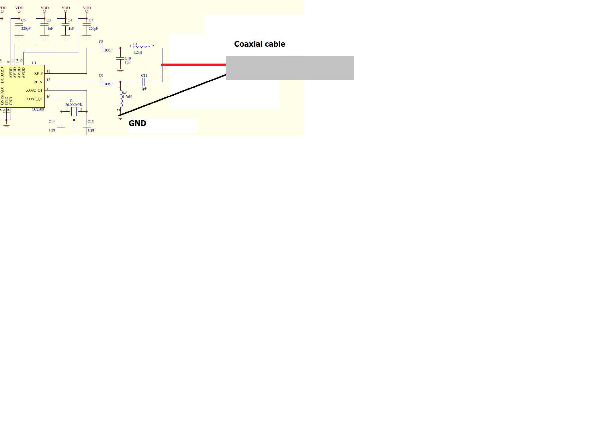
 I have tried to tune the matching component by use VNA to measure the impedance.  I soldered the coxial pigtail after the PI matching network. And I thought I can measure the Rx input impedance as CC2540 stay in receive mode at most of the time. 

 Oddest thing was the measured impedance keep the same no matter CC2540 is power off or power on.  So I am not sure if it's helpfull or right way to tune the component for matching by using the VNA? 

 But I try to tune the component by using the VNA to measure S11 anyway. After I finish tuning, S11 is lower than -10dB, I can measure the output power is about 4.2dBm. But there is no way I could measure the receive performance(rx sensitivity). That's I am not sure whether the tuning is good by only verify the input S11? Tx performace is easy to measure but how about the rx performance?

  Adding to the measured impedance keep the same no matter power off or power on. I don't trust the tuning result at all. And also the field test proved that performance is not good. Our application is setup a bidirection datalink between CC2540 and IPAD. The distance is only about 20meters.

  Does anyone could give me hints on tuning the component for matching or the LC balun?

  Thank you for your help,

 Derek

  • Hi Derek,

    Derek Deng1 said:
    Oddest thing was the measured impedance keep the same no matter CC2540 is power off or power on.  So I am not sure if it's helpfull or right way to tune the component for matching by using the VNA? 

    You should clearly see the RX filter bandwidth as a dip in the S11 trace when the radio is in continuous RX. I would recommend controlling the chip from SmartRF Studio to make sure the radio is actually in RX.

    The balun used in the reference designs is derived through numerous measurements in the lab including load- and source-pull and has been verified through output power and sensitivity measurements. The balun is very robust towards component tolerances and also variances in the PCB. Our recommendation is thus to copy the reference balun as closely as possible.

    Derek Deng1 said:
     But I try to tune the component by using the VNA to measure S11 anyway. After I finish tuning, S11 is lower than -10dB, I can measure the output power is about 4.2dBm. But there is no way I could measure the receive performance(rx sensitivity). That's I am not sure whether the tuning is good by only verify the input S11? Tx performace is easy to measure but how about the rx performance?

    Your output power seems good, and this should also indicate, but not guaratee, that the sensitivity is also ok. One way to measure the sensitivity is to connect one CC2540 board to another with coaxial cables, run the PER test in SmartRF Studio and gradually insert more attenuation between the boards.

    Derek Deng1 said:

    Adding to the measured impedance keep the same no matter power off or power on. I don't trust the tuning result at all. And also the field test proved that performance is not good. Our application is setup a bidirection datalink between CC2540 and IPAD. The distance is only about 20meters.

      Does anyone could give me hints on tuning the component for matching or the LC balun?

    The problem here is probably not the balun but the impedance of the antenna. The output of the reference balun (including the T-filter) is very close to 50 ohm, so this should thus be the input impedance of the antenna. Solder you coaxial pigtail to the antenna feed point and measure S11. You can tune the antenna by inserting series and/or shunt matching components or reduce the antenna length if it is a PCB antenna.

    You can also have a look at this app note for details: http://www.ti.com/litv/pdf/swra161b

    Cheers,
    Fredrik

  • Hi, I would like measurement s11 parameter of my wireless system with cc2500. Do I have to connect a coaxial cable with impedance 50ohm instead of the last componenti of the balun? Thanks you Best Regards
  • Hi Gianfranco,

    I assume you want to measure the antenna impedance. In that case you remove the last series component of the balun and solder a semi rigid coaxial cable to the antenna-side pad.

    Cheers,

    Fredrik

  • Hi Fredrik

    I would measurement output power of radio cc 2500 without antenna. For do this, I should remove the PI filter balun, antenna and connect with a coaxial cable between l1 and c11? as Show in the picture?

     
    Thank you
    Best Regards

     
  • Ok. You should connect after the PI-filter. By looking at the reference design this seems to be the 50-ohm point.

    Cheers