


Doing project on CC2541 using BLE. So I use OSAL and other pre-made goodies from TI. I now try to generate IR signals on P1_0 using Timer 0 channel 2 and never got it working properly. Including many other problems I observe output with ghost delays like shown on this oscillogram:
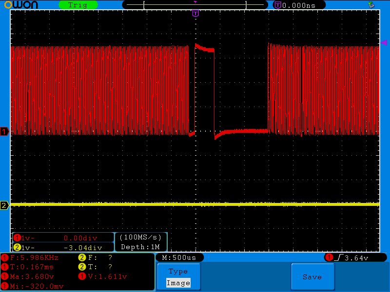
This all makes me think that BLE stack or OSAL is trying to use Timer 1 too. Meanwhile I found no information what timers are used by OSAL and what are pitfalls. Relevant code is included. I run Timer 1 from system clock divided by 8. T1CC0 is 100. This all should give 25kHz clock I think. I actually get 38kHz and very weird but cycle length is "floating" on oscilloscope screen.
void HalIrSendInit( void ) {
 /* Set pin direction to Output */
 P1DIR |= BV(0); // 0 is input, ->1<- is output
 PERCFG |= BV(6); // Timer 1 alternative location 2
 P2DIR |= BV(6) | BV(7); // PRIP0 to 11, 1st priority: Timer 1 channels 2-3
 P2SEL |= BV(3); // Timer1 priority over USART0
 P2SEL &= ~BV(4); // Timer1 priority over Timer4
 P1SEL |= BV(0); // P1_0 is peripheral, not GPIO

 T1CTL |= BV(2); // Timer 1 is system clock divided by 8
 T1CTL |= BV(1) | BV(0);// Up, down mode
 T1CCTL2 |= BV(2); // Compare mode, channel 2
 T1CCTL2 |= BV(5) | BV(4); // -----Toggle output
 T1CCTL2 |= BV(6); // Enable interrupt for Timer 1, channel 2

 /* Double this number, impulse get double longer too. */
 const uint16 period=80;
 const uint16 periodhalf=period/2;
 const uint8 PERIODL=(period & 0xFF);
 const uint8 PERIODH=(period >> 8);
 const uint8 PERIODLhalf=(periodhalf & 0xFF);
 const uint8 PERIODHhalf=(periodhalf >> 8);
 // L must be written first and H after.
 T1CC0L=PERIODL; //
 T1CC0H=PERIODH; // These two register define lenght of cycle. 100% of time

 T1CC2L = PERIODLhalf; // PWM signal period
 T1CC2H = PERIODHhalf; //

}
I think gurus here know what I do wrong or can recommend what part of documentation I missed.
