This thread has been locked.

If you have a related question, please click the "Ask a related question" button in the top right corner. The newly created question will be automatically linked to this question.

The operation is abnormal when change the button SW_2 of CC2541 keyfob from P0_1 to P1_5.

Other Parts Discussed in Thread: CC2541

Hi , I am use CC2541 Keyfob board and the project that I use is Keyfob project.

In normal operation, the CC2541 keyfob board will advertising when I push the button SW_2 at P0_1.

I have another CC2541 board , it also use the keyfob project at C:\Texas Instruments\BLE-CC254x-1.3.2\Projects\ble\KeyFob\CC2541DB.

And the pin of button at this CC2541 board is P1_5.

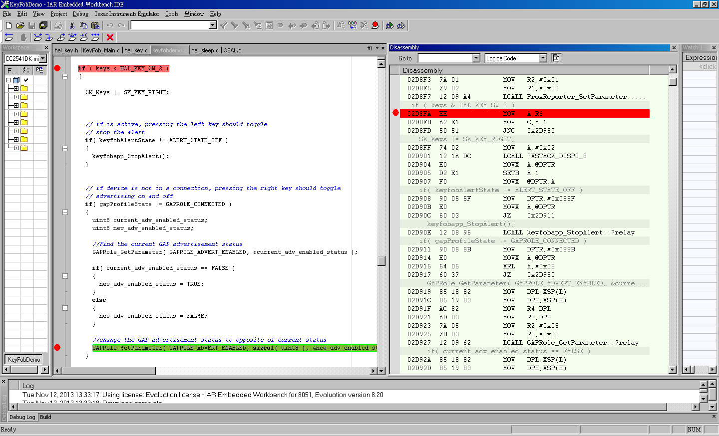
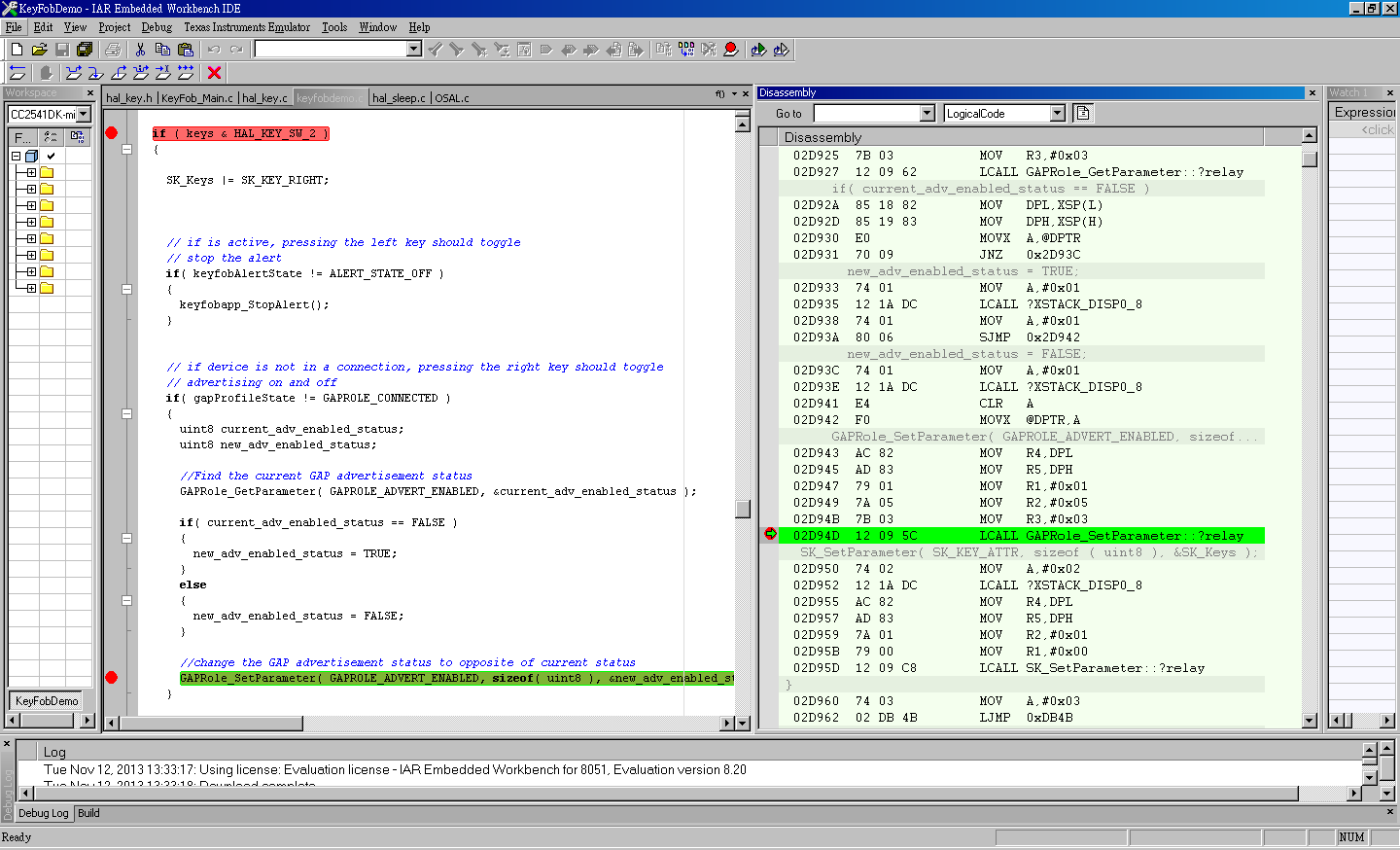
But I change the pin of SW_2 from P0_1 to P1_5 like the following code at hal_key.c , the CC2541 keyfob board will auto advertising after ten second when power on.

/* SW_2 is at P0.1 */
/*#define HAL_KEY_SW_2_PORT P0
#define HAL_KEY_SW_2_BIT BV(1)*/
#define HAL_KEY_SW_2_PORT P1
#define HAL_KEY_SW_2_BIT BV(5)

The question is:

Does any else should I modify but I didn't modify in hal_key.c or in keyfobdemo.c ??

or something I have to notice at change the pin od SW_2 at CC2541 ??


Thank for your direction.

Martin

  • Does anyone can answer the question ??

    Thanks !!

  • You also need to change the following defines

    #define HAL_KEY_SW_2_IEN      IEN1  /* CPU interrupt mask register */
    #define HAL_KEY_SW_2_ICTL     P0IEN /* Port Interrupt Control register */
    #define HAL_KEY_SW_2_ICTLBIT  BV(1) /* P0IEN - P0.1 enable/disable bit */
    #define HAL_KEY_SW_2_IENBIT   BV(5) /* Mask bit for all of Port_0 */
    #define HAL_KEY_SW_2_PXIFG    P0IFG /* Interrupt flag at source */

  • Hi , YiKai

    Thanks for your direction !

    I have try to modify the code like the following if I want to change the PIN of HAL_KEY_SW_2 from P0_1 to P1_5

    #define HAL_KEY_SW_2_PORT P1
    #define HAL_KEY_SW_2_BIT BV(5)


    #define HAL_KEY_SW_2_SEL P1SEL
    #define HAL_KEY_SW_2_DIR P1DIR

    #define HAL_KEY_SW_2_IEN IEN1             /* CPU interrupt mask register */
    #define HAL_KEY_SW_2_ICTL P1IEN        /* Port Interrupt Control register */               
    #define HAL_KEY_SW_2_ICTLBIT BV(5)    /* P0IEN - P0.1 enable/disable bit */      
    #define HAL_KEY_SW_2_IENBIT BV(5)      /* Mask bit for all of Port_0 */
    #define HAL_KEY_SW_2_PXIFG P1IFG     /* Interrupt flag at source */                        

    and the P0INT_VECTOR is modify to P1INT_VECTOR.

    but the button still without any operation , does something wrong at my modify ??

  • 1. You miss the following two defines:

    #define HAL_KEY_SW_2_EDGEBIT  BV(2) //Check "PICTL"
    #define HAL_KEY_SW_2_EDGE     HAL_KEY_FALLING_EDGE

    2.  Your define of HAL_KEY_SW_2_IEN and HAL_KEY_SW_2_IENBIT are wrong. They should be like the following two defines:

    #define HAL_KEY_SW_2_IEN      IEN2  /* CPU interrupt mask register */
    #define HAL_KEY_SW_2_IENBIT   BV(4) /* Mask bit for all of Port_1 */

    You should check CC253x/4x user guide for those register settings.

  • Thanks for you , YiKai !

    I have check the user guide , but I don't know how to modify parameter when I use Pin P1_5... 

    And I have try to modify the code like the following , but it doesn't work .

    #define HAL_KEY_SW_2_PORT             P1
    #define HAL_KEY_SW_2_BIT                 BV(5)

    #define HAL_KEY_SW_2_SEL                P1SEL
    #define HAL_KEY_SW_2_DIR                 P1DIR

    #define HAL_KEY_SW_2_IEN                 IEN2                     // CPU interrupt mask register
    #define HAL_KEY_SW_2_ICTL               P1IEN                    // Port Interrupt Control register
    #define HAL_KEY_SW_2_ICTLBIT         BV(5)                     // P0IEN - P0.1 enable/disable bit
    #define HAL_KEY_SW_2_IENBIT           BV(4)                     // Mask bit for all of Port_0 
    #define HAL_KEY_SW_2_PXIFG            P1IFG                   // Interrupt flag at source

    #define HAL_KEY_SW_2_EDGEBIT        BV(2)
    #define HAL_KEY_SW_2_EDGE              HAL_KEY_FALLING_EDGE

    And I seen other statement , should it modify the P0INT_VECTOR to P1INT_VECTOR in HAL_ISR_FUNCTION ??

    and modify the PICTL |= HAL_KEY_SW_1_EDGEBIT; to  PICTL |= HAL_KEY_SW_1_EDGEBIT | BV(2); ??

    I set the breakpoint at if ( keys & HAL_KEY_SW_2 ), and it call this function after 10 seconds when power on.

    And the information at breakpoint like the picture.


    Set the breakpoints at  if( current_adv_enabled_status == FALSE ) , and the picture is like the following:

    I am new to this ,so I didn't know what it mean...

    and the button at Pin P1_5 still without any operation , and it will be trigger after 10 seconds when power on.

    Does there has other code will trigger the P1_5 in Keyfob project ??

    Please help me to solves this problem , thanks for everybody !!

  • 1. Do you change HAL_ISR_FUNCTION( halKeyPort0Isr, P0INT_VECTOR ) to HAL_ISR_FUNCTION( halKeyPort1Isr, P1INT_VECTOR )?

    2. Check if there is high/low status change on P1_5 when you press the button.


  • Yes , I have change HAL_ISR_FUNCTION( halKeyPort0Isr, P0INT_VECTOR ) to HAL_ISR_FUNCTION( halKeyPort1Isr, P1INT_VECTOR )?

  • Do you check if P1_5 has high/low status change when the button is pressed? You can set a break point at HAL_ISR_FUNCTION to see if it is triggered when button is pressed.

  • I add the following code and it is work

    HAL_ISR_FUNCTION( halKeyPort1Isr, P1INT_VECTOR )
    {
    HAL_ENTER_ISR();

    if ((HAL_KEY_SW_2_PXIFG & HAL_KEY_SW_2_BIT))
    {
    halProcessKeyInterrupt();
    }

    /*
    Clear the CPU interrupt flag for Port_0
    PxIFG has to be cleared before PxIF
    */
    HAL_KEY_SW_2_PXIFG = 0;
    HAL_KEY_CPU_PORT_1_IF = 0;

    CLEAR_SLEEP_MODE();

    HAL_EXIT_ISR();

    return;
    }

    But I have another question , I have add the PTM mode in Keyfobdemo.c when P0_4 is low.

    And in the PTM mode , the LED will turn on when I push the button.

    At the CC2541 Keyfob board , the LED will turn on when P0_1 is low. It is work!!

    if ( P0_1 == 0)
    {
    // turn the Green LED on
    HalLedSet( HAL_LED_1, HAL_LED_MODE_ON );
    i++; 
    }

    But I change the P0_1 to P1_5 , the LED doesn't turn on when I push the button.

    Can I use the parameter of "P1_5" to determine P1_5 is low or high ???

    And I have try to use the if(keys & HAL_KEY_SW_2) ,but it is not working in KeyFobApp_ProcessEvent.


    Does there has other method the determine the Pin P1_5 is low or high ??

  • Yes, you can use P1_5 to read GPI status directly.  I suggest you to set a breakpoint at if(P1_5==0) to check the value of P1_5.

  • The value of P1_5 always show '.' (0x01)

  • If press or release the button, P1_5 is still 0x01. I would suggest you to check HW first.

  • If the P0_4 is high in my code , It will not entering the PTM mode and run normal procedure.

    But I set the break point at if ( keys & HAL_KEY_SW_2 ) and use debug to check , it will call  if ( keys & HAL_KEY_SW_2 ) and start advertising when I push the button.

    So it can work at normal mode , does it still has problem in HW ??

  • You should change "if ( keys & HAL_KEY_SW_2 )" to "if (P0_5==0)".

  • Thanks for you ,YiKai.

    I have try , and it has working.

    By the way...

    Can I change the name of CC2541 keyfob via Android 4.3 by using the UUID(0x2A00) of Device Name ??

  • In my case I forgot to change HAL_ISR_FUNCTION( halKeyPort0Isr, P0INT_VECTOR ) to HAL_ISR_FUNCTION( halKeyPort1Isr, P1INT_VECTOR ) in hal_key.c. Now it is working. Thank you.