This thread has been locked.

If you have a related question, please click the "Ask a related question" button in the top right corner. The newly created question will be automatically linked to this question.

Connecting CC2540EM with CC Debugger

Other Parts Discussed in Thread: CC2540, CC2530

Hi, I have tried several times without lucky so I need to ask to experienced guys.

I have the CC2540EMK and the CC Debugger, I like to flash the CC2540 and always have the red light in the Debugger.

My questions are:

1. In the CC2540EMK includes 2 board, Master and Peripherial, what is the difference between them?

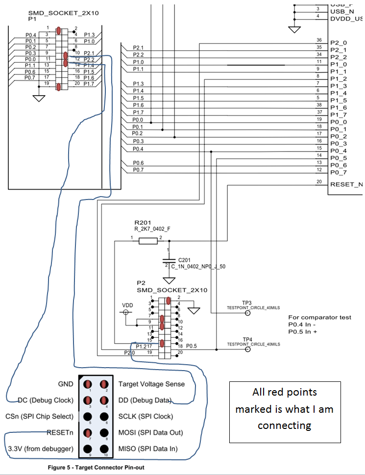
2. I am attaching an image with my connections, probably I am missing something, please let me know if it is correct or not? And if so, what will be the physical points that I need to check in the CC2540EM to see if it is working properly?

I am supplying 3.3v for both (CC2540EM and CC Debugger)

Please help me because I do not know what else I need to do

Thanks

  • Hi Osvaldo,

    1) I believe there is no difference between the two CC2540EMs included in the CC2540EMKit.

    2) a) How do you supply voltage to the CC2540EM? An option is to use CC Debugger to power the target

    b) Target Voltage Sense should be connected to the target's VDD. This signal is used by the CC Debugger's level shifters and nothing will work without it being connected to something.

    Have you considered the System-on-Chip battery board? (SOC-BB). It is made for use with EMs like CC2540 + CC Debugger and may make your life easier.

    Br,
    TIABO 

  • Hi TIABO,

    Thanks for your answer, it helps a lot.

    By the way I have another doubt, it is regarding programming the Soc, Can I use any 8051 software to flash the chip?

    Thanks in advance I really appreciate your support

    Osvaldo

  • I'm not exactly sure what you mean when you ask "can I use any 8051 software to flash the chip", but I'll give it a shot:

    The 8051 CCxxxx devices from Texas Instruments uses a proprietary debug interface (read e.g. application note SWRA410. Look also at the literature it refers to to learn more about the debug interface)

    In other words, you can use any flash programmer tool that supports 8051 chips from TI, i.e. this debug interface. On top of my head, I can unfortunately not recall other software than the SmartRF Flash Programmer, though.

    Br,
    TIABO

  • Thanks for your answer TIABO, sorry if my question was a little confusing.

    My doubt is about if I can use any 8051 compiler in order to create the .hex file to flash the CCxxxx? any suggestion? 

    I get now that for debug interface I need a proprietary software.

    Thanks for your support

    Regards,

  • The IDE you use must support the 8051 Texas Instruments devices, IAR Embedded Workbench supports all of them.

    If that's the case and it can generate .hex files, then you should be able to download the image using SmartRF Flash Programmer. Of course, IDEs also offer "Download to target" functionality.

    Br,
    TIABO

  • Hi Osvaldo,


    In theory you should be able to use any 8051 compiler. You can check out the Contiki CC2530 project for SDCC for inspiration:

    http://processors.wiki.ti.com/index.php/Getting_started_with_Contiki_and_CC2530

    https://github.com/contiki-os/contiki/tree/master/cpu/cc253x

    One snag here is that the TI stacks are only supported by IAR, so you cannot use the BLE stack llibraries with SDCC. For proprietary stuff however you should be ok.

    I also highly recommend ordering the SoC Batteryboard. Without seeing your setup I guess the red_LED issue is due to a wrong or missing connection.


    Cheers,

    Fredrik