This thread has been locked.

If you have a related question, please click the "Ask a related question" button in the top right corner. The newly created question will be automatically linked to this question.

CC2540 Keyfob and dongle both not detected by CC Debugger

Other Parts Discussed in Thread: CC2540, CC2541, TPS62730

Hello,

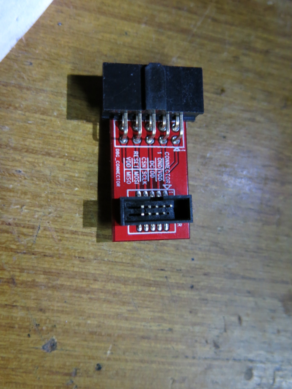
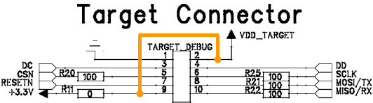
Some time back I bought CC2540 mini kit and tried the preloaded demo applications using btool and it worked. Now i wanted to program it with my custom application but CC debugger is not detecting keyfob as well as dongle.

I followed exact steps mentioned in Mini Development Kit User’s Guide but cc debugger is not detecting any of the chip, i have already searched forum for possible issues and also verified cable orientation but nothing worked, cc debugger light always remains red.

can anyone please advice what I am doing wrong, i have made video of the issue if anyone would like to see:

dongle issue: http://www.youtube.com/watch?v=6509FfiEkFc

keyfob issue: http://www.youtube.com/watch?v=qYcJUcyBGWk

Thank you

  • Hi,

    Have you modified the CC Debugger? The reason I ask is because it should not be able to power the Keyfob per default. Originally, you would have to power the CC2540 Keyfob by a battery while connected to a CC Debugger. It's not ideal, an many engineers modify the CC Debugger to power the keyfob, and at the same time breaks something.

    Based on the video (Dongle version link is broken by the way) I have to assume that the CC Debugger is malfunctioning.

    Best Regards

    Joakim

  • Hello Joakim,

    Thank you for your reply.

    No I have not modified CC Debugger, i just took out CC Debugger from its packing for programming only.

    Initially i tried using battery but it didn't worked so as mentioned in user guide i did shorted the R1 pad beside debugger connector on the keyfob.

    this is the video link for usb dongle error: http://www.youtube.com/watch?v=6509FfiEkFc

    please advice if its possible to get debugger replaced, i have bought it 5-6 weeks before only.

    Thank you

    Pranav

  • Hi Pranav,

    Seems like you have connected the debugger correctly  to the dongle. Can you please check if the cable is OK? Use a multimeter to verify connectivity from one end of the cable to the other (measure from the debug connector on the dongle to the pins on the small adapter board between the debugger and the cable).

  • Hi,

    Is your CC Debugger detected when you connect it to a PC? If you install SmartRF Flash Programmer, does the CC Debugger appear in the list of devices? Please make sure you upgrade to the latest firmware revision.

    It may be that a level shifter is broken. When CC Debugger is connected to the target, do you measure ~3.3V on pin 2, VDD_TARGET? Do you have an oscilloscope, can you measure the RESET, DC and DD signals (pins 7, 3 and 4) when pressing the CC debugger reset button?

    Please see the CC Debugger User's Guide for schematics (SWRU197).

    Br,
    TIABO

  • Hello

    Thank you for your replies.

    While checking continuity i found that pin 2 on small adapter board is missing, please see below picture.

    for all other pins i got continuity from dongle pins to mini adapter board pins.

    also when connected to PC CC debugger shows in smartRF flash programmer, please see this picture:

    pin2 voltage on dongle is 3.3v, I don't have oscilloscope this time but i measured voltages using multimeter on pin 3,4 and 7, its 3.2v

    Thank You

    Pranav

  • Hi,

    Pin 2 is the "target voltage detect" pin for the CC Debugger level shifters. Without it it will not detect a target.

    You can work around this by shorting pin 2 (VDD_TARGET) with pin 9 (+3.3V) on the CC Debugger. This tricks the level shifters into believing the target runs at 3.3 V.

    This of course has a limitation: With this workaround, you must power the target at 3.3 V (+/- 0.3 V)!

    The safest is to power the target using the CC Debugger.

    Br,
    TIABO

  • Hi TIABO,

    We have designed a test fob similar to CC2541 key fob and I have a few questions.

    1) The CC debugger sees (green light) the TI key fob but did not on our custom fob until I tied sense pin 9 of debug connector to VCC on pin2 as you suggest above and powered our custom fob with the CC debugger. The debugger would not recognize the CC2541 if using battery to the TPS62730 and creating 2.1V (red light). Is the CC Debugger supposed to work OK when the TPS62730 is regulating down to 2.1V?


    2) Next using current firmware download for keyfob, (with POWER_SAVING and DC_DC_PO7 disabled) we could get our fob to advertise, connect and send button presses. Why do we have to disable to get it to work is my question. Can you explain?

    Thanks for your consideration of my questions.

    Patrick
  • Hi Patrick,

    I think that there is digital levels mismatch in this case as the CC debugger expects a 3.3V HIGH LEVEL but the CC2541 HIGH LEVEL is at 2.1V and vice versa.


    But well as the TPS is used for power optimization it can be disabled during debugging and enabled for final application.

    Regards,

    Amjad

  • Hi Patrick,

    Please start a new thread for new questions instead of "hijacking" old threads :]

    1:
    Pin 9 on the debug connector ("sense") is used to level shift signals to/from the CC2541 interfacing CC debugger.
    If you have tied it to the supply of the debugger at 3.3V the level shifters might have issues detecting a 2.1V input as a valid digital "1".

    Ideally the output of the DC/DC should probably be connected to pin 2.

    2:

    This is often related to the sleep timer not running properly. When POWER_SAVING is defined the sleep timer clock is derived from the 32768Hz crystal oscillator. Please check that it is running properly.


    Regards,
    Svend