This thread has been locked.

If you have a related question, please click the "Ask a related question" button in the top right corner. The newly created question will be automatically linked to this question.

Incorrect / drifting frequency with CC2564 on custom board

Other Parts Discussed in Thread: CC2564

I have a similar/same problem as stated in this thread:

http://e2e.ti.com/support/low_power_rf/f/660/t/310584.aspx

I have custom hardware with a CC2564. For a test after my hardware was not discoverable with the stack running I tried a CW test.


There I found, that the TX frequency was everything, but not what I set up in the command. To easily identify the frequency in the 2.4GHz band I set up the powerlevel to 15, what obviously (as stated in the thread above) is not the best idea. After lowering the powerlevel I get similar results, the frequency is not what is set up on one board, on the other board it is on the right spot, but the amplitude is veeery low ( about -95dBm when placing it closely to the Wi-Spy)

Can it be that the high power level destroyed something, like the bluetooth chip, or something on the way to the antenna? (I use more or less the reference design)

I send the following commands to the Chip:

TX: 01 84 FD 0C 00 00 4E 06 00 00 00 00 00 00 00 00

RX: 04 0E 04 01 84 FD 00

TX: 01 01 FF 06 0C 18 19 00 01 01

RX: 04 0E 04 01 01 FF 00

TX: 01 80 FD 06 FF FF FF FF FF 01

RX: 04 0E 04 01 80 FD 00

as found in a testing PDF.

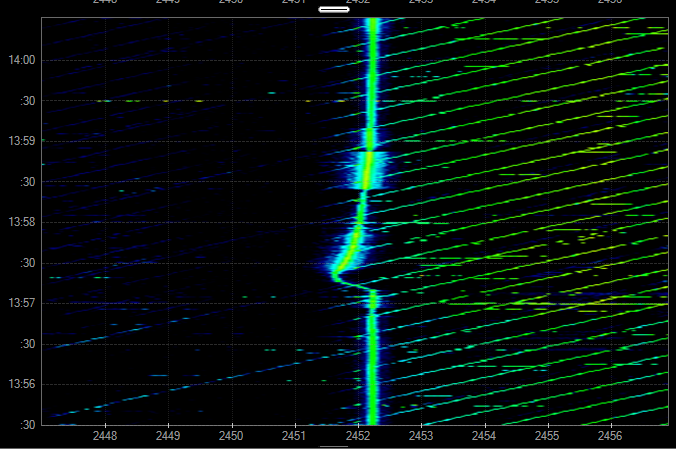
Instead of seeing something at 2479MHz currently the frequency is at 2452,33 MHz with a high temperature dependence (heating the pcb with the finger can shift the frequency by several MHz)

I also observed once, that the frequency hopped to the right spot, and was stable there, but hopped back to the instable state occasionally.


So where can I search for a solution? Currently I only have these two boards, the next batch is comming next week, so I can test them without setting them to powerlevel 15 before.

Thanks for the advice!

Edit: Attatced example of heating the bluetooth chip with a finger (probably only 2-3°C)

  • Hello,

    Drifting frequency issue: Are you using the same 26 MHz crystal from NDK and 12 pF caps as shown on the data sheet?  Is your PCB close to what TI suggested?  BTW, in my view it would be better to use a VCTCXO at 26 MHz rather than a 26 MHz crystal.

    Low power issue: You probably have a broken cap, BPF, bad solder joint on IC or another part, etc.  Do you have any RF test equipment to help troubleshoot the issue?

    Regards,

    Eric Hooker

    RF/Microwave Consultant

    http://www.linkedin.com/in/erichookerrfconsultant


  • Hello,

    thanks for your advice. Yes I use almost identically the reference design. I use the NX2016SA with 12pF caps, as stated in the reference design. It runs smoothly at 26MHz.


    I fixed the low power issue by replacing the cap. The voltage rating of this cap was 25V, maybe not enough at the highest power level?!

    So this Module seems to work fine, but I am still not discoverable.

    But the first one is still doing this crap with the drifting Frequency. I hope that with the next batch of PCBs I can tell more, since two parts, which also have been misused, are not telling much about the reason why they failed.

    But it is still seems strange to me, that one module was able to get to the right frequency, and then switch back to the wrong behaviour. What is the reason for this behaviour? I think TI must have encountered this (because they say that powerlevel 14 and 15 should not be used in the thread above). So what part of the design does influence this behaviour?

    Thanks!

  • Hello,

    Which Service Pack version are you using?

  • I used the files from http://processors.wiki.ti.com/index.php/CC256x_Downloads

    for the CC2564

  • Hi,

    Thanks for the response. 

    Regarding the power level I will check and get back to you.


    Regarding the discoverable problem see below:

    Usually discoverable problem happens because of using the wrong Service pack.

    As from the link you have provided it looks like you are using “CC256XQFNEM” is it revision 1.2 or 1.2B?

    If not sure, can you please provide the HCI Read Local Version Information value(see below) to check if you are using CC2564B or CC2564 http://processors.wiki.ti.com/index.php/CC256x_Testing_Guide#UART_Communication


    If you are using the CC256xB device you need to add the below patch if you are using Bluetopia

    http://processors.wiki.ti.com/index.php/CC256x_MSP430_Bluetopia_Basic_Demo_APPS#CC256XB_Information

    If not you have to download the CC2564B service pack.

  • This is the respone i get upon the hci_read_local_version_information:

    0x04,0x0E,0x0C,0x01,0x01,0x10,0x00,0x06,0x00,0x00,0x06,0x0D,0x00,0x0F,0x1B


    This should be the CC2564 device, but I am failing to interpret this respone.

  • Hi,

    Regarding the power level there is no limitation you can use 14 and 15 as well.

    and from the output you have posted it looks like you are using CC2564(0x1B0F ) and not CC2564B(0x1B90)


  • I checked back, I am using the bluetooth_init_cc2564_2.12.bts service pack. So that should be fine?

    Why does the thread which I linked above state that powerlevel 14 and 15 should not be used (with the PAN1326 module) ? Is this connected to some hardware reasons? So on which hardware properties does the availability of the powerlevels depend? What is the critical design parameter? Because there is of course the posibility that there is something wrong / not optimal in my design, but I need a starting point to work on to improve it.

  • Hi,

    As I mentioned in the previous post there is no limitation you can use 14 and 15 as well.

    That was a mistake made in the other thread.