This thread has been locked.

If you have a related question, please click the "Ask a related question" button in the top right corner. The newly created question will be automatically linked to this question.

battery monitoring using internal ADC in cc2540

Other Parts Discussed in Thread: TPS62740, CC2540

Hi,

      I have designed to measure the battery voltage level of Li-ion poly of 70mAh operates from 2.7v-4.2v charging using USB 5v. Charging circuit is stable.

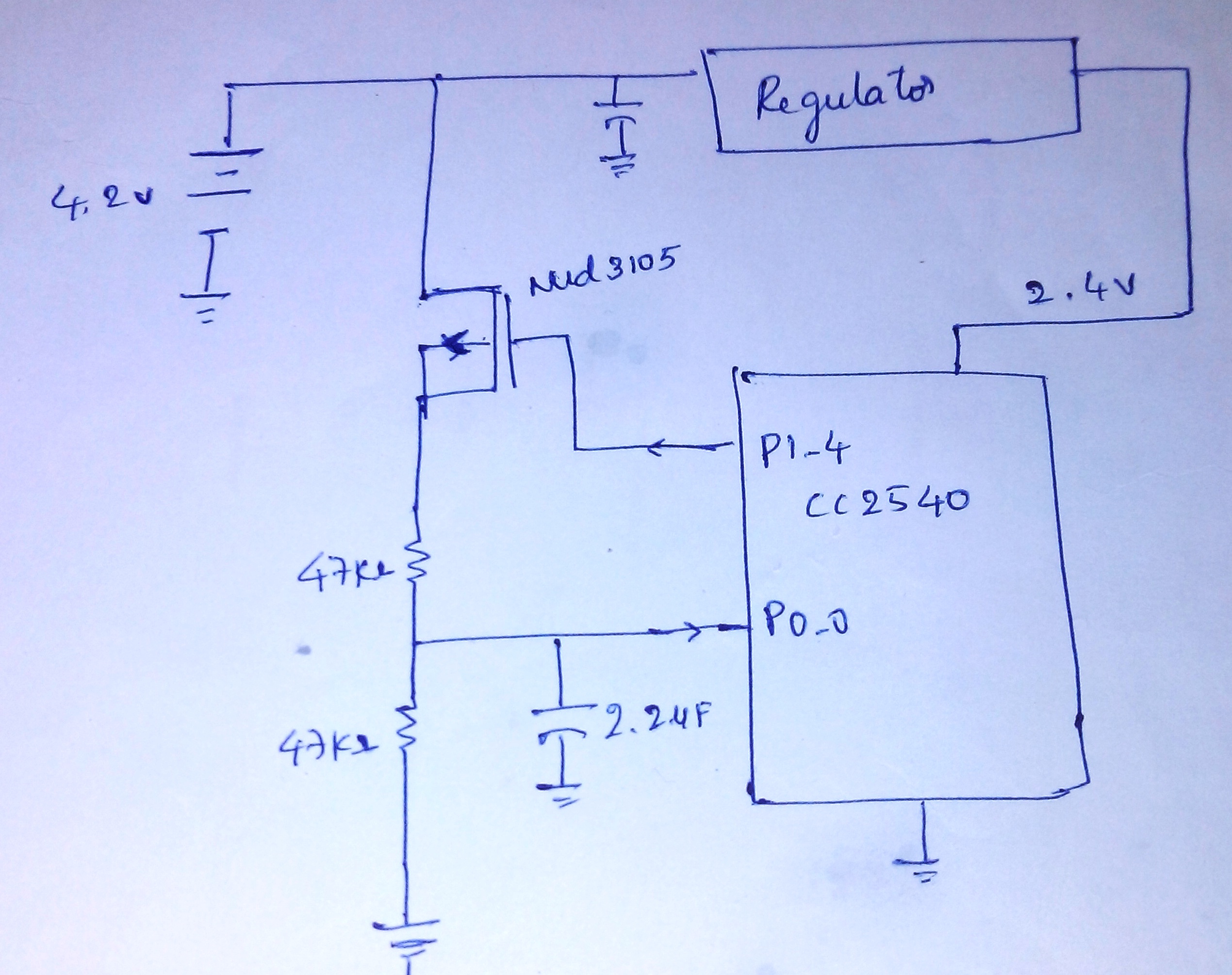
i want to know my design will be stable on not?. i measured the voltage using internal adc @ 30ms interval & latched the mosfet 2ms before to read the ADC.  i have used TPS62740 since i am using Li-ion battery.

i tried with different resistor value for voltage divider circuit to match 176K Ohms, not successful. but 47KOhms  gave me good results.  
suggestion are most welcome.
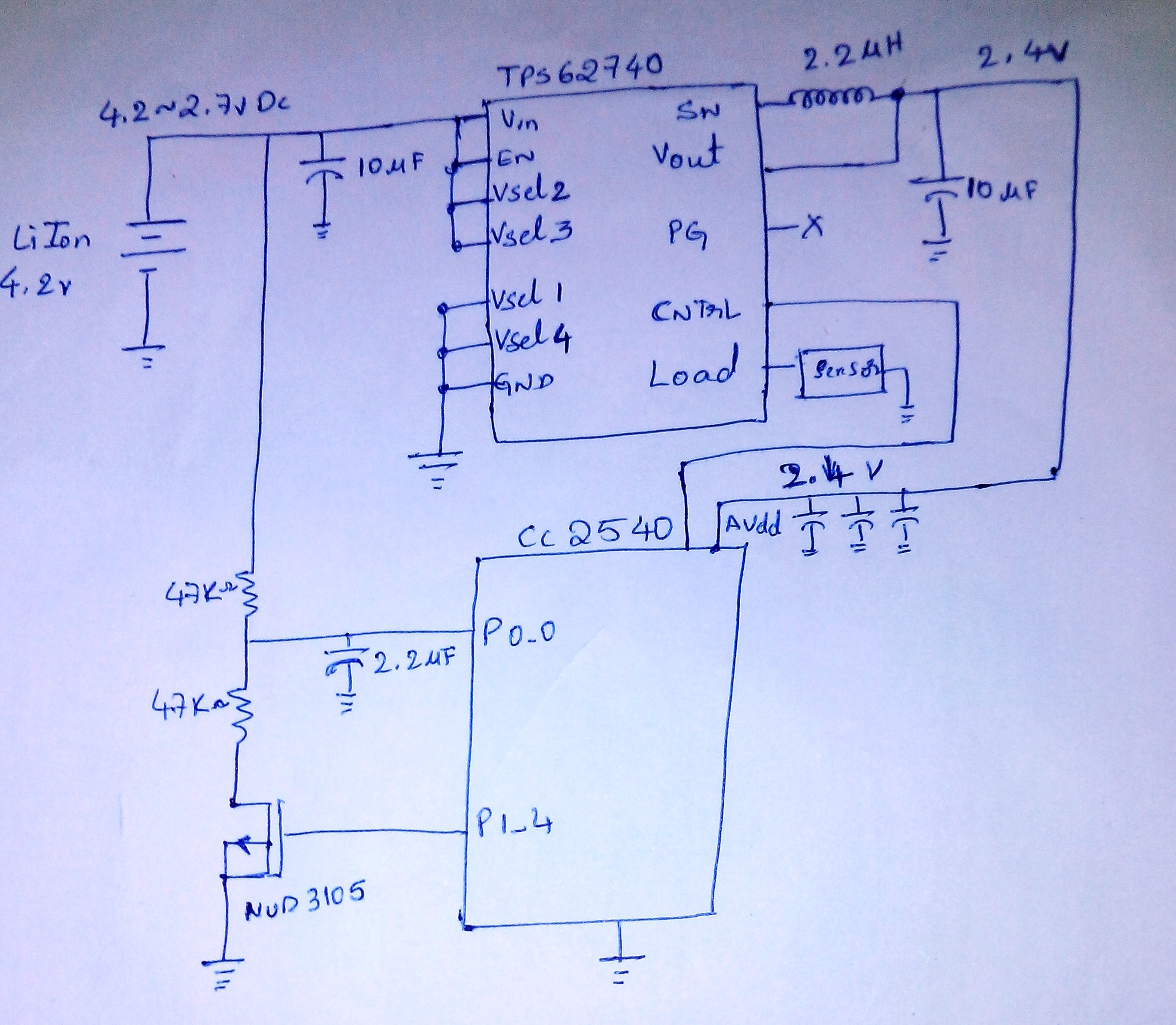
  • Hello Seetharam,

    Have a look at the following post.  It also includes a spreadsheet from a TI member for creating the the voltage divider circuit.

    http://e2e.ti.com/support/amplifiers/precision_amplifiers/f/14/t/214907.aspx

    Thanks,

  • Hi Greenja, 
    Thanks.

    i was trying to match the impedance of internal ADC of cc2540 which says 176Kohms according to user guide. i used two 180kOhms for voltage divider but it required more latching time to mosfet to get accurate results. 

    i need to read the voltage level @100ms duration and voltage should be VDD/2, where 180KOhms didn't gave stable results. 

  • Hello,

    Well I can honestly say I have never worried about matching the impedance of the internal ADC, especially when measuring less than 5 volts on the CC2540.  My primary concern was getting the voltage converted to a 0 to 3.1V in for a full range reading and not exceeding the max current rating of the port pin.

    Thanks,

  • Hi Seetharam,

    As you already have figured out you should use resistors which are significantly smaller than the input resistance of the ADC. 47k is in the range we normally recommend.

    One issue with you circuit is that when the transistor is off, no current flows through the resistors and you will get the battery voltage directly on the IO-pin. The best way to do this is to use a PMOS instead, but you will need to add a NPN-transistor to drive this.

    Cheers,

    Fredrik

  • Thanks  Greenja,

    Yes i'll take care of the max current flow rating of the MCU port  which is 50uA in my circuit. as spec seems my circuit doesn't exceed maximum rating.


  • Hello Fredrik K,

    Thanks for the valuable input. this design was mention earlier in the forum, but was not clear.

    i tried using 2 transistor it worked. but to reduce the BOM cost went up with one, but forget consider to isolate the direct battery voltage to the port.
    nud3105 is relay driver.

    i just modified my circuit below, is that recommended? 

    Thanks in advance 

  • Hi Fredrik,

    is the NPN transistor really needed with CC2540? Why one can not just drive the P channel MOSFET directly with IO port through e.g. 1 KOhm resistor to the ground. Yes, the logic is then inverted.

    Regards,

    Jernej

  • Hi Fredrik,

    please ignore my previous reply. Of course NPN transistor is needed. I missed out different supply voltages. Apologies.

    Regards,

    Jernej

  • Hello,  I am using the following circuit to measure the battery voltage using the ADC of the CC2540.  The battery voltage range that I am measuring is between 3.6V to 6.0V.   I am using an npn transistor and MOSFET to control when I measure the voltage via the voltage divider.  The resistor values of the voltage divider are 64.9K and 15K.  For a 6.0V input voltage I expect the input voltage to the ADC to be approximately 1.126volts which it is.  When we enable the ADC to make a measurement the voltage input to the ADC increases to 1.980 volts.  Any idea why we are seeing this behavior in our circuit.  A PDF of schematic with battery monitor circuit is also attached.

    Thanks,

    James

     Sheet 3.pdf

  • Hi,

    What is the voltage of the cap C9? Try removing it and check.

    Have you configured internal Vref to some voltage?

    Regards,

    Vijay

  • Hi James

    When u turn on the npn transistor, Capacitor  will be in charging cycle (voltage in ramp up).

    give some time (5-100ms) to stabilize across capacitor and measure  adc. Hope will give correct reading.

    try using internal 1.24v as reference.