I am having trouble reliably receiving advertising packets with a CC2541/CC2590 board that closely follows the reference design. So, I’ve been testing and studying what I can observe, including the various control lines. Please review below and tackle the embedded questions.
Thanks
The below results were obtained with the CC2541/CC2590 board running the SimpleBLEcentral code with minimal changes:
-
Code was added to restart the scan when it ends
-
Code was added to configure the CC2541 to use the CC2590
Figure 1 below shows the CC2590 PA Enable line and the LNA Enable line and a trace showing a spectrum analyzer output showing some RF activity.

Question 1: The LNA trace shows a pattern where the LNA is on for around -9ms and then off for ~2ms... and this repeats. Is the pattern seen on “LNA Enable” due to switching frequencies?
Question 2: If so, why is the LNA off for such a long time? (~ 2mS) The CC2541 can switch frequencies very quickly.
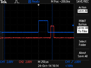
Figure 2 below shows a zoom of the interesting area on the right side in Figure 1.

Question 3: Does the labelling/understanding shown in Figure 2 look correct?
Figure 3 below shows the approximate 2ms “down time” on the LNA in blue along with the capture of three typical advertising packets shown under the red line. (A wide RBW was used to vaguely capture the other advertising channels.) This shows how the long “down time” can swallow up an advertising event and thus miss it.

Question 4: The range extender configuration command HCI_EXT_ExtendRfRangeCmd does NOT properly configure line HGM (P1_1). After running the command the HGM (P1_1) is always low. I find that I need to manually set it high with these lines (P1SEL &= ~0x02; P1DIR |= 0x02; P1 |= 0x02;). However, this is not ideal because it is permanent and therefore not change dynamically as needed. How do I configure the CC2541 to automatically control the HGM line?
Also, note that it appears that a lot of the advice given about configuring the range extender for the CC2541 does not appear to comport with the CC2541 spec. In particular, these sources...
...specify “RFC_OBS_CTRLx” settings that do not exist table provided on page 334 of the CC2541 spec. (Some of the recommended settings do appear in the CC253x table… which is confusing.) I have not been successful in my efforts to manually configure the three range extender control lines using the RF observable configuration registers.