


hi,
I have 2 device CC2540 and CC2541keyforb.
I want to interface sensor, which give me data on RX/TX pin of uart.
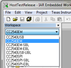
For this what project I need from the following project which is available at location: C:\Texas Instruments\BLE-CC254x-1.4.0\Projects\ble.
I read the user guuide named as CC2540/41 System-on-Chip Solution for 2.4-GHz Bluetooth® low energy Applications and understand which configuration i need. but where I have to intialize and where I can use API's like UART_Write() or UART_Read that i can't understand.
After flashing the program i Connect hardware in following manner.
1. I draw two wire from CC2540 test pin P0.2,P03 for Rx/Tx and connect it to Rx/Tx of USB-RS232 connector.
2. i draw two wire from CC2540 VCC and GND from CC2540 Debug pins (pin 1 and pin2) and connect it to VCC,GND of USB-RS232 connector.
then connect serial cable to PC serial port. and open hyper terminal with desired setting like COM1, desired baud rate, parity and flow control are none and 1 start and stop bit.
But after doing this when I connect CC2540 to PC USB port of PC, I don't get any data(writteb on UART using HAL_UARTWrite API) on hyperterminal which I open.
I do following Code :
------------------------------------------------------------------------------------------------------------------------
In new file uart.c:
/****************************************************************************
* Clock setup
* See basic software example "clk_xosc_cc254x"
*/
// Set system clock source to HS XOSC, with no pre-scaling.
CLKCONCMD = (CLKCONCMD & ~(CLKCON_OSC | CLKCON_CLKSPD)) | CLKCON_CLKSPD_32M;
// Wait until clock source has changed.
while (CLKCONSTA & CLKCON_OSC);
/* Note the 32 kHz RCOSC starts calibrating, if not disabled. */
/***************************************************************************
* Setup I/O ports
*
* Port and pins used by USART0 operating in UART-mode, at the Alternative 1
* location are:
* RX : P0_2
* TX : P0_3
* CT/CTS : P0_4
* RT/RTS : P0_5
*
* These pins must be set to function as peripheral I/O to be used by UART0.
* The TX pin on the transmitter must be connected to the RX pin on the receiver.
* If enabling hardware flow control (U0UCR.FLOW = 1) the CT/CTS (Clear-To-Send)
* on the transmitter must be connected to the RS/RTS (Ready-To-Send) pin on the
* receiver.
*/
#if (chip==2541 || chip==2543 || chip==2545)
// Configure USART0 for Alternative 1 => Port P0 (PERCFG.U0CFG = 0).
PERCFG = (PERCFG & ~PERCFG_U0CFG) | PERCFG_U0CFG_ALT1;
#endif
#if (chip==2541)
// Give priority to USART 0 over Timer 1 for port 0 pins.
P2DIR &= P2DIR_PRIP0_USART0;
#elif (chip==2543 || chip==2545)
// Give priority to USART 0 over Timer 1 for port 0 pins.
PPRI &= ~PPRI_PRI0P0;
#endif
#if (chip==2541 || chip==2543 || chip==2545)
// Set pins 2, 3 and 5 as peripheral I/O and pin 4 as GPIO output.
P0SEL |= BIT5 | BIT4 | BIT3 | BIT2;
#elif (chip==2544)
// Set pins 1, 2 and 3 as peripheral I/O and pin 0 as GPIO output.
P0SEL0 = 0x11; // Map P0_0 and P0_1 as UASRT0.
P0SEL1 = 0x11; // Map P0_3 and P0_2 as UASRT0.
#elif (chip == 2540)
// Configure UART0 for Alternative 1 => Port P0 (PERCFG.U0CFG = 0)
PERCFG &= ~0x01;
// Configure relevant Port P0 pins for peripheral function:
// P0SEL.SELP0_2/3/4/5 = 1 => RX = P0_2, TX = P0_3, CT = P0_4, RT = P0_5
P0SEL |= 0x3C;
// Configure relevant Port P1 pins back to GPIO function
P1SEL &= ~0x3C;
#endif
#if (chip==2541 || chip==2543 || chip==2545)
// Initialize P0_1 for SRF05EB S1 button.
P0SEL &= ~BIT1; // Function as General Purpose I/O.
P0DIR &= ~BIT1; // Input.
#elif (chip==2544)
// Initialize P0_1 for SRF05EB S1 button.
P0SEL0 &= ~P0SEL0_SELP0_1;// Function as General Purpose I/O.
PDIR &= ~PDIR_DIRP0_1; // Input.
#endif
/***************************************************************************
* Configure UART
*
*/
// Initialise bitrate = 57.6 kbps.
U0BAUD = UART_BAUD_M;
U0GCR = (U0GCR & ~U0GCR_BAUD_E) | UART_BAUD_E;
// Initialise UART protocol (start/stop bit, data bits, parity, etc.):
// USART mode = UART (U0CSR.MODE = 1)
U0CSR |= U0CSR_MODE;
// Start bit level = low => Idle level = high (U0UCR.START = 0).
U0UCR &= ~U0UCR_START;
// Stop bit level = high (U0UCR.STOP = 1).
U0UCR |= U0UCR_STOP;
// Number of stop bits = 1 (U0UCR.SPB = 0).
U0UCR &= ~U0UCR_SPB;
// Parity = disabled (U0UCR.PARITY = 0).
U0UCR &= ~U0UCR_PARITY;
// 9-bit data enable = 8 bits transfer (U0UCR.BIT9 = 0).
U0UCR &= ~U0UCR_BIT9;
// Level of bit 9 = 0 (U0UCR.D9 = 0), used when U0UCR.BIT9 = 1.
// Level of bit 9 = 1 (U0UCR.D9 = 1), used when U0UCR.BIT9 = 1.
// Parity = Even (U0UCR.D9 = 0), used when U0UCR.PARITY = 1.
// Parity = Odd (U0UCR.D9 = 1), used when U0UCR.PARITY = 1.
U0UCR &= ~U0UCR_D9;
// Flow control = disabled (U0UCR.FLOW = 0).
U0UCR &= ~U0UCR_FLOW;
// Bit order = LSB first (U0GCR.ORDER = 0).
U0GCR &= ~U0GCR_ORDER;
in board Config file (iocc2540.h):
// U0CSR (0x86) - USART 0 Control and Status
#define U0CSR_MODE 0x80
#define U0CSR_RE 0x40
#define U0CSR_SLAVE 0x20
#define U0CSR_FE 0x10
#define U0CSR_ERR 0x08
#define U0CSR_RX_BYTE 0x04
#define U0CSR_TX_BYTE 0x02
#define U0CSR_ACTIVE 0x01
// U0UCR (0xC4) - USART 0 UART Control
#define U0UCR_FLUSH 0x80
#define U0UCR_FLOW 0x40
#define U0UCR_D9 0x20
#define U0UCR_BIT9 0x10
#define U0UCR_PARITY 0x08
#define U0UCR_SPB 0x04
#define U0UCR_STOP 0x02
#define U0UCR_START 0x01
#define U0GCR_ORDER 0x20
#define U0GCR_BAUD_E 0x1F
---------------------------------------------------------------------------------
Can anyone tell me where and how I have to change for UART Communication through CC2540.
please provide hardware connection detail as well if possible.
reply as soon as possible because i am stuck in this since 1.5 months.
The image of USB-rs232 converter which I use is attached here:

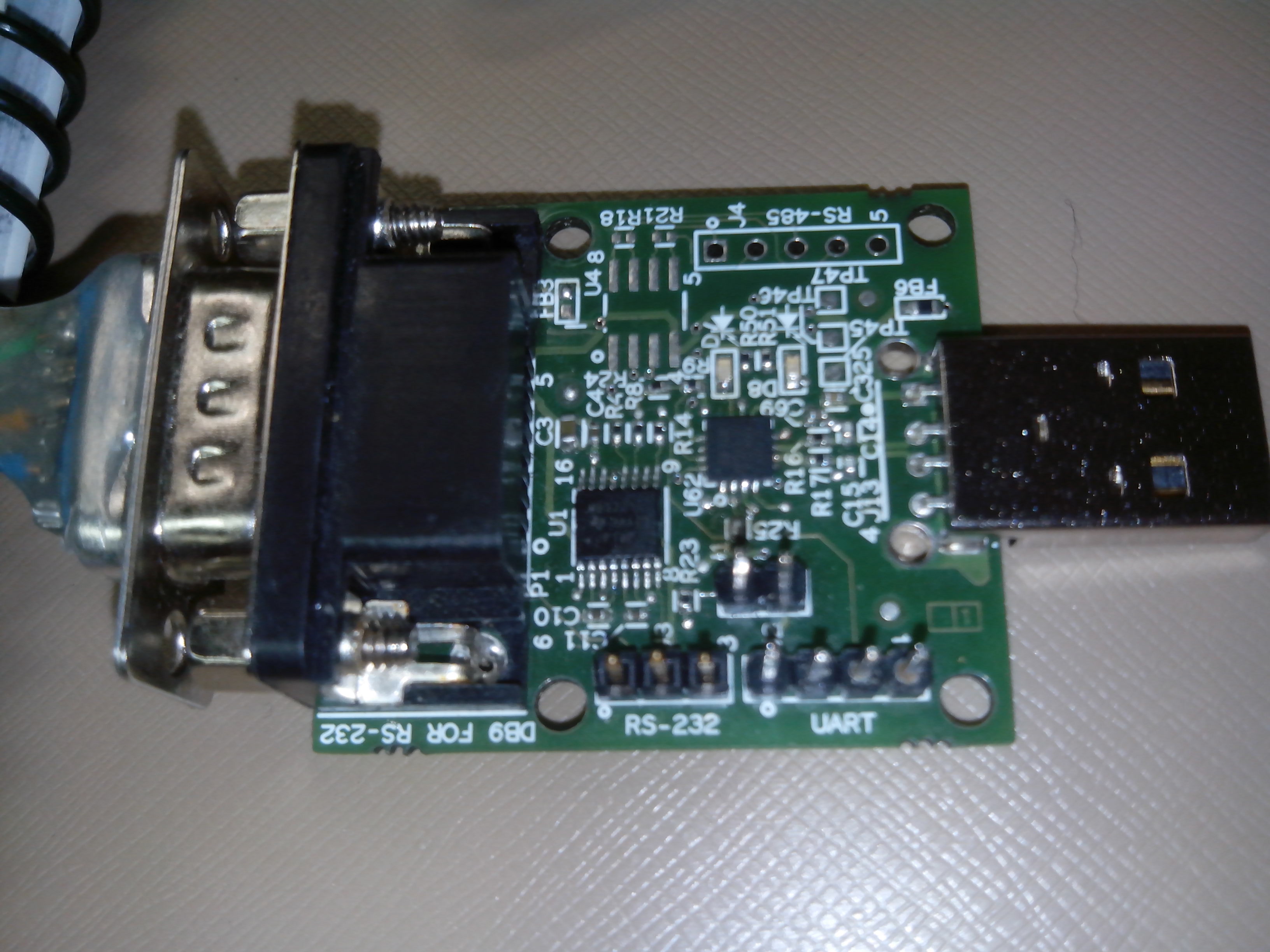