This thread has been locked.

If you have a related question, please click the "Ask a related question" button in the top right corner. The newly created question will be automatically linked to this question.

Begin programming cc2541

Other Parts Discussed in Thread: CC2541

hi guys, i'm trying to program a Beacon based on CC2541 soc and BLE stack1.4.

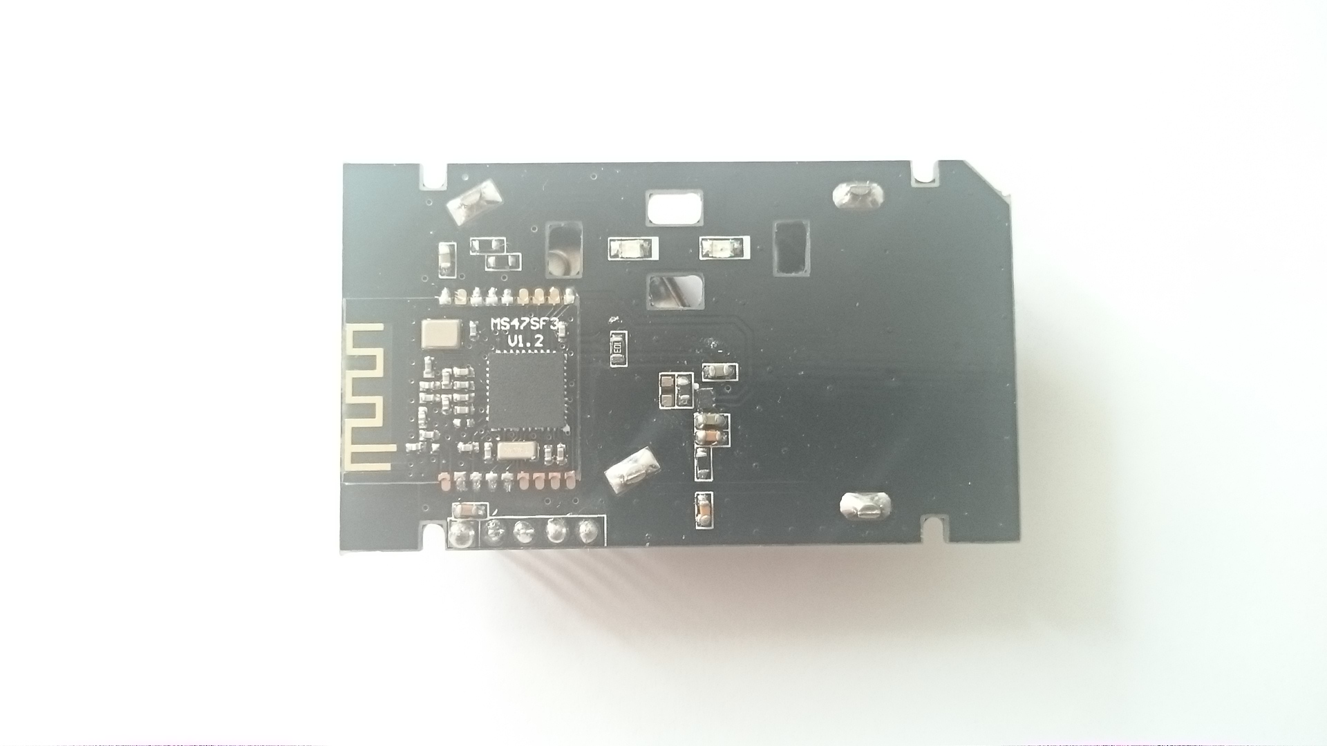
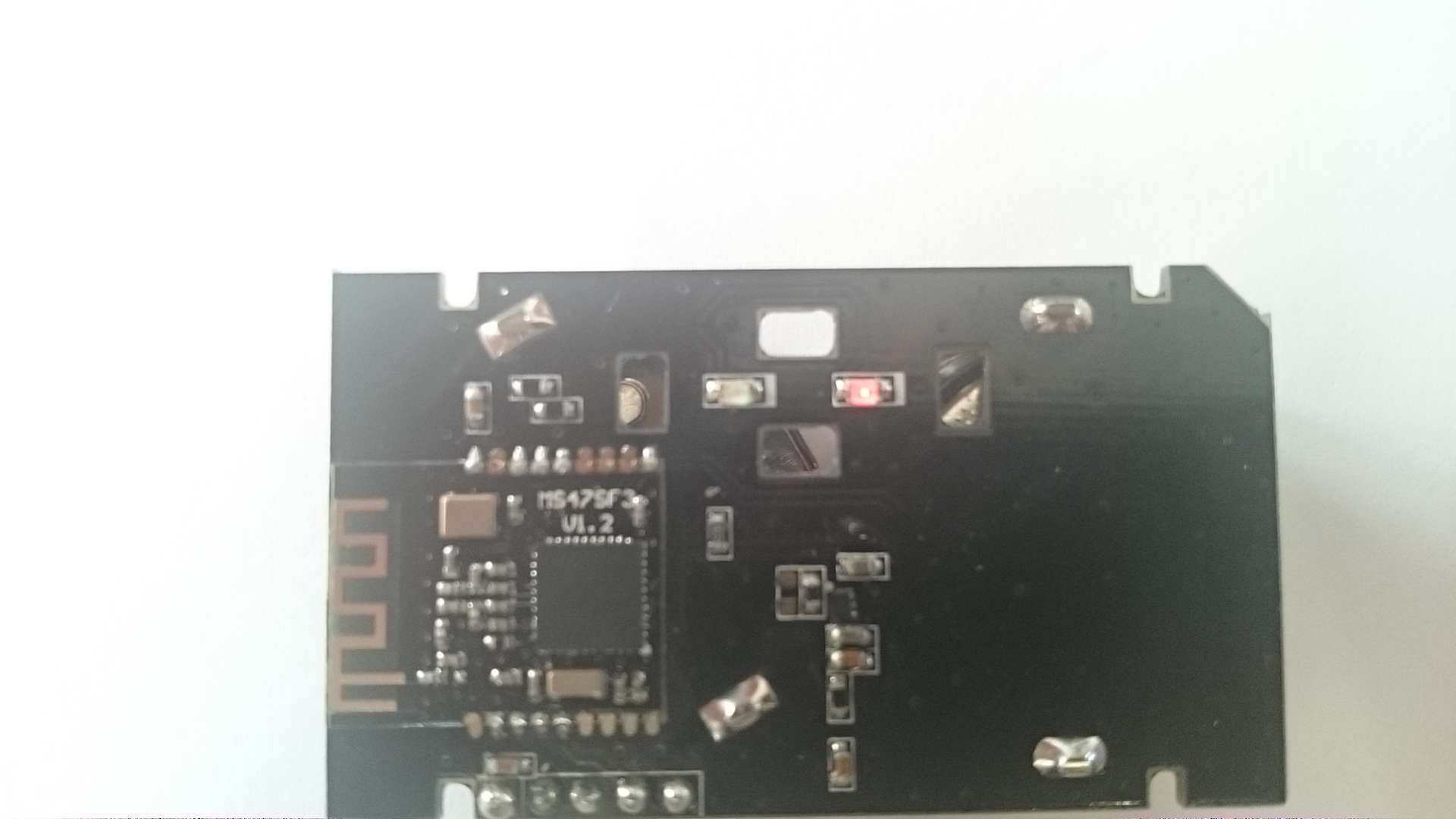
I have Minew Beacon with two Led and one KEY.

I've seen the examples that are in folder BLE after installation BLE Tool, but it's very hard because I have never had experience programming firmware.

So i explain we that is my target.

I wolud have a beacon that advertisement indefinitely, so i can get the rssi value for distance calculation.

for this i've find GAP_ADTYPE_FLAGS_GENERAL.

Now to understand the basic concepts, i would turn on or turn off the two led installed on my board when i tun on or turn off my boad used key.

After i'm flashing the firmware simpleBLEPeripheral i can see the red light fixed on, and it's don't change even if edit the code below

HalLedSet( (HAL_LED_1 | HAL_LED_2), HAL_LED_MODE_OFF );

there is a method or service that returns the state or the presence of KEY or LED or other peripheral and at which port, of cc2541, their are connected?

  • Hi,

    Not familiar with your board. The SimpleBLEPeripheral project we release in our SDK works out of the box with our development kits, either the Keyfob or the SmartRF board. Perhaps their LEDS are mapped to different IOs on their board. Good to double check and compare with our dev kits.
    See here for reference:
    processors.wiki.ti.com/.../CC254X_Overview
  • My friend you are doomed. You are not going to get good technical support from Texas Instrument. Their support documents are written by nerds. My suggestion to you is to switch to a different chip from different manufacturer with good support as soon as possible. You will waste alots of time looking for help on this forum. 

    For example, Read the following link for the request efforts that people have made before and nobody answered them . You will lots of unanswered or poorly answered requests. 

    http://e2e.ti.com/support/wireless_connectivity/f/538/t/301589

    Think positive and do not waste your time and energy on this forum. 

    best,

    jess

  • can explain me how it possibile to change the setting of ports?

    i've read P0DIR,P0SEL etc etc but i don't understand what it means.

    in addiction to what is the programming procedure or guide to add service? 

  • Hi Valerio,

    Let me explain meaning of the registers and how it is helpful in setup the GPIO:

    1. First of all you need to device whether you want to use particular pin as GPIO or as special purpose. That you can do using PxSEL register. Here 'x' mean port number, I mean for Port0 it is P0SEL, P1SEL for Port1, so on. Let say if you want to use P0.0 as GPIO set that bit to 0 OR if you want to use it as special purpose set that bit to '1', as shown below:

    P0SEL &= 0xFE; // Set P0.0 as GPIO

    P0SEL |= 0x01; // Set P0.0 as Special Purpose

    2. Now set the direction i.e. Input/Output using PxDIR register. Set particular bit to '0' to configure as Input OR set it to '1' to configure it as Output.

    P0DIR &= 0xFE; // Configures P0.0 as Input

    P0DIR |= 0x01; // Configures P0.0 as Output

    3. And to set the value on particular pin use Px register.

    P0 &= 0xFE; // Write '0' on P0.0

    P0 |= 0x01; // Write '1' on P0.0

    Hope this helps.

    Thanks,

    Dhaval

  • Dhaval thanks for your reply... i will try to use it for modify the code.
  • ok i've change the value of register because the led are connected to pin p0.1 and p0.2.
    thanks dhaval.

    Now i think that the key is connected on pin p0.3 and i wolud turn on or turn off the board by pressing the button.
    can suggest me.

    you could show me how to try to achieve this.

    I've find the register HAL_KEY and PWRMGR but i don't undestand how manage the procedure (callback, preiodic scan event, interrupts.
  • Hi Valerio,

    I think you can configure Falling/Rising edge interrupt on that particular pin. And in ISR you can take necessary action.

    Thanks,
    Dhaval
  • Hi Valerio,

    Once again I see that you ask questions similar to what i am looking for.... (Minew board)
    I am trying to write code to support the on-board button.
    I tried using all available pins one after the other in keyfob sample and none of then triggered the event.

    1. how did you figure out that the button is connected to pin 0.3? (we use different voard but it might be the same... board design related to the pins)
    2. did you manage to support the button on your board?
    3. can you advice me for the right parameters for supporting the key press?

    Thanks!