This thread has been locked.

If you have a related question, please click the "Ask a related question" button in the top right corner. The newly created question will be automatically linked to this question.

CC2541 does not transmit with an integrated balun

Other Parts Discussed in Thread: CC2541

Hello all,

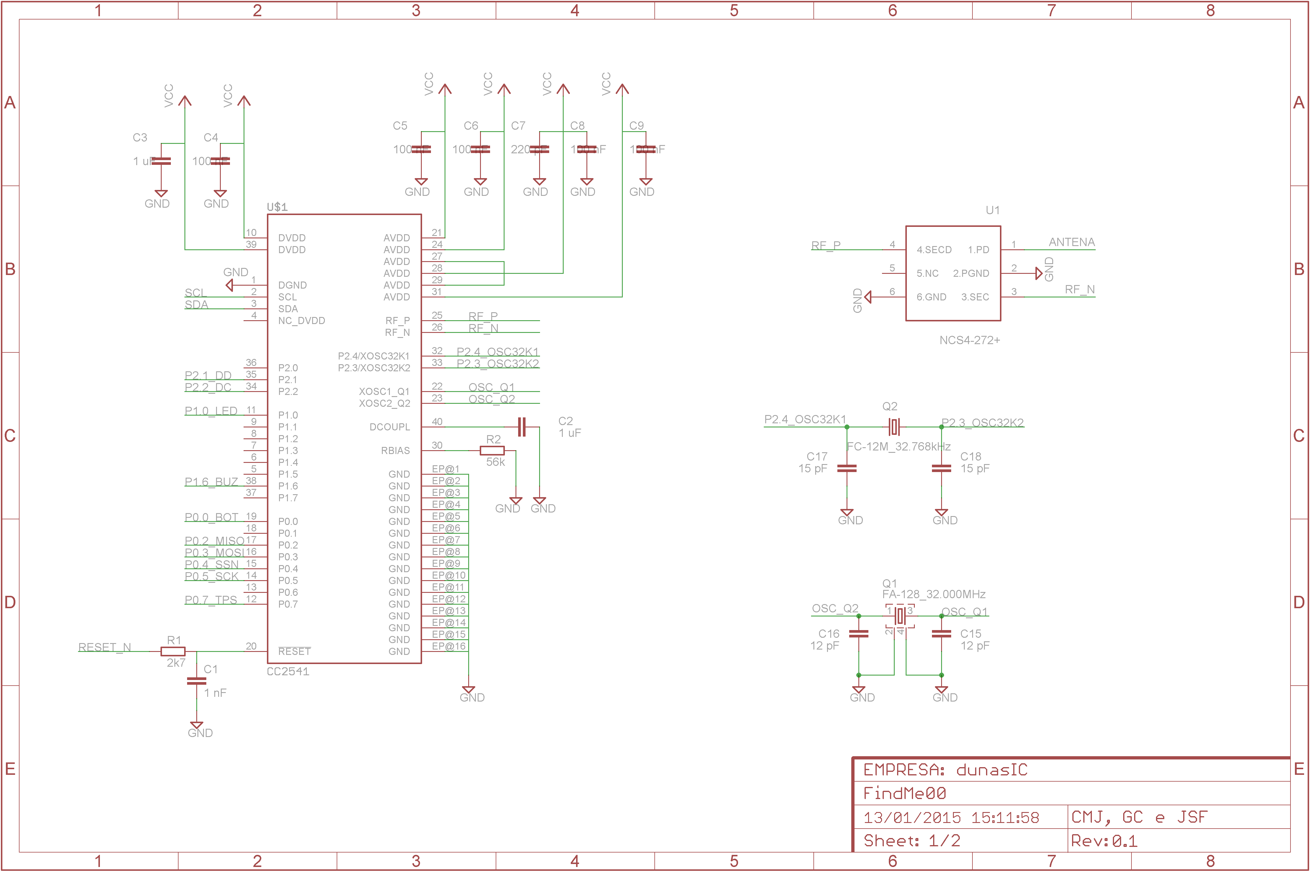
I have built two PCBs housing the CC2541F256 chip, one with a discrete component matching network, and another with a NCS1-292+ Mini-Circuits balun.

When I program both boards with the same code version, only the former board appears to transmit. Using the USB Dongle + BTool to check if the boards are discoverable, I detect only the first one.

A curious thing that I noticed is that both chips are sending the advertising data, as I check the current consumption on the oscilloscope (using a 10 Ohm resistor at the power input of the board). The picture below shows in green the waveform for the first board, with discrete matching network, and the yellow one shows the current waveform for the second board, with the integrated balun.

I also checked that both oscillators (32 kHz and 32 MHz) are properly working. 

I was having an issue before that probably the CC2541 has not been properly initialized. When I turned the second board on, it did not generate the advertising packets, and kept consuming a constant 10 mA current. After reading some forum discussions, I raised the 'HAL_SLEEP_ADJ_TICKS' from its default value 25 to 50, and this problem was solved, although no transmission was detected.

Has anyone here experienced similar issue?

Thank for your attention.

Best regards,

Jose Sales

  • Hi Jose,

    Can you post the relevant schematic?

    Best wishes
  • Hello JXS,

    Thanks for the quick response.

    I followed basically the application circuit suggested on the CC2541 Keyfob reference design, just replacing the matching network with discrete components to the integrated balun. Hereby are the schematic sheets:

    PS.: I actually used the NCS1-292+ balun instead of the NCS4-272+ stated on the schematic above. Both baluns operate @ 2.4 GHz and have really similar characteristics.

    Best regards,

    Jose Sales

  • Hi Jose,

    First off, the NCS1-292+ is not matched to the CC2541 so you will most likely get a performance loss by using this balun. There are baluns made for the CC2541 from Johanson, Murata and TDK which I would rather recommend using.

    Second, I do not think you have connected the balun correctly. The datasheet says that pins 2 and 5 should be grounded and that 6 is NC. You have grounded 6 and left pin 5 floating. The datasheet also says that pins 2, 3 and 4 (balanced connection and ground) are DC connected. This basically means that you must add DC-blocking capacitors on the balanced input to avoid the balun messing of the DC bias of the RF pins.

    Cheers,
    Fredrik

  • Hello Jose and Fredrik,

    I was actually checking the balun from Mini Circuits, Johanson and Murata and all of them seem to fit quite well the application. All of them have the same impedance (100 Ohms for the differential input and 50 Ohms for the single output) and even the same footprint.

    Regarding the decoupling capacitors, the application notes from TI AN107 (which seems to be writing by Fredrik) says that there is no need for DC caps. Or is that only for Murata's and Johanson's baluns? 

    So I didn't understand well the last post... Could you, please, be more specific? Thank you!

    Cheers,

    Carlos Mendes

  • Hi Carlos,

    The Murata balun described in AN107 does not have 100 ohm differential impedance, it is matched to the complex output impedance of the CC2541. Same goes for the specific components by Johanson and TDK made for the CC25xx device family.

    These specific baluns also have internal DC blocking capacitors. The datasheet for the Mini Circuit part clearly states that this is not the case for that part. The RF pins will have a certain DC bias voltage and if the balun has a DC path to ground you will get unwanted results such as no transmission at all.

    Cheers,
    Fredrik
  • Hello Fredrik and Carlos,

    Thanks for the positive feedback you have sent.

    Regarding the topics you have come up with, I have made a simple test to check whether the baluns work properly: firstly, I removed the original balun from the USB Dongle PCB (it is not really clear whether it is a Murata or Johanson or TDK), and put the Minicircuits one instead. The USB Dongle appears to work properly.

    Then, I put the Dongle balun at my PCB, and surprisingly it didn't work at all.  

    In order to solve this issue once for all, I got access to a spectrum analyzer to check the RF signal at the antenna output by means of an inductive testing probe. With the analyzer set to maximum hold setting, I tested both the working PCB and the malfunctioning one (marked with the red arrow in the picture below).That's the result I got:

    We can clearly see that there is a 2.28 MHz frequency shift between the signals. I wonder why that happens, because that is clearly the reason that the Dongle can't find the signal from the PCB.

    Best regards,

    Jose Sales

  • Hi Jose,

    In that case I would check the frequency offset of your crystal.

    BR,
    Fredrik
  • Hello Fredrik,

    Thanks for the continuous reply.

    I was also suspicious about the crystal, and it had indeed a relatively high frequency deviation (measured via oscilloscope). I replaced the 32 MHz crystal and I finally managed to detect the board! 

    The RSSI value that I read via BTool of this board was pretty low though. When I tested the other board made with the discrete balun, it already got a transmission power 6 dB lower compared to the transmission power of the evaluation Keyfob board. The read RSSI value of this integrated balun board is even lower than the discrete balun counterpart...

    In this opportunity, I would like to ask regarding the PCB antenna. I followed the AN043 Application Note (www.ti.com/.../swra117d.pdf) to design the PCB antenna, and I noticed that the proposed antenna seems to be a little different compared to the one that comes on the Keyfob and USB Dongle boards. Does that somehow explain that great loss of performance?

    Best regards,

    Jose Sales

  • The antenna resonance frequency will depend on the size of the GND plane. The antenna must thus be matched for different designs to get the optimum performance and explains the different antenna length for the different design. For more info on antenna matching, see AN058, www.ti.com/.../swra161b.pdf