Hi,
in the SWCU117a data sheet for the cc26xx there is command COMMAND_MEMORY_READ (page 677) mentioned but there is no description of the command. From TI's support I received short description:
This command reads a specified number of elements with a specified access type (8- or 32 bits) from a specified memory mapped start address and returns the read data in a separate communication packet. The requested amount of data must be less than the max size of a communication packet.
The specified Access Type must be either 0 or 1. The value of 0 forces 8-bits read accesses. The value of 1 forces 32-bits read accesses. The specified Number of Accesses gives the number of 8- or 32-bits read accesses. Max value for Number of Accesses is 63 for Access Type = 1.
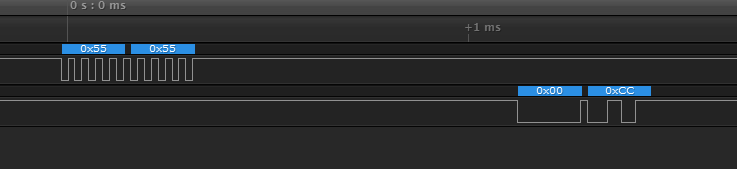
The format of the packet including the command is as follows: unsigned char ucCommand[9];
ucCommand[0] = <size=9>;
ucCommand[1] = <checksum>;
ucCommand[2] = COMMAND_MEMORY_READ;
ucCommand[3] = Memory Map Address [31:24];
ucCommand[4] = Memory Map Address [23:16];
ucCommand[5] = Memory Map Address [15:8];
ucCommand[6] = Memory Map Address [7:0];
ucCommand[7] = Access Type [7:0];
ucCommand[8] = Number of Accesses [7:0];
However it doesn't provide receipt of how to read the actual value from memory. I attempted to follow the algorithm provided for command COMMAND_CRC32 but it didn't work. Can you describe details of the algorithm which would let me know how to read the data after sending the request?
Regards,
Maciek