This thread has been locked.

If you have a related question, please click the "Ask a related question" button in the top right corner. The newly created question will be automatically linked to this question.

Current consumption - CC2650EM-7ID

High everyone,

I measured the current on SmartRF06 Evaluation board with the CC2650EM-7ID configured to advertise every 30 seconds. Parameters are below and system configuration is from the Simple Peripheral project :

// Advertising interval when device is discoverable (units of 625us, 160=100ms)
#define DEFAULT_ADVERTISING_INTERVAL            320
// Advertising timeout, then wait until defaut_advertising_timeoff is reached
#define DEFAULT_ADVERTISING_TIMEOUT		1	
// Advertising timeoff, after advertising timeout
#define DEFAULT_ADVERTISING_TIMEOFF		30000 
// General discoverable mode advertises indefinitely
#define DEFAULT_DISCOVERABLE_MODE             GAP_ADTYPE_FLAGS_LIMITED

I measured the current on the EM board with a small current amplifier (the dedicated chip is not present on my board...) and a LeCroy WaveAce 1002. Voltage output is set to 1mV / uA.

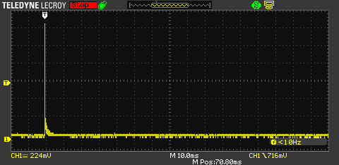
Here is the result : 

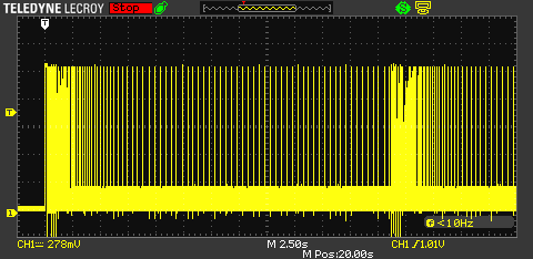
We can see the advertising at the beginning (board powered on) and at the end (30 seconds later), but what the hell is all this behaviour between ? I measure a current of 1.4mA (maximum for my uA amplifier with 1mv/uA - ) and the mean current consumption is really high and far from the 1.5 - 3 uA I should have is these conditions.

The device work correctly, I can see it with my smartphone and connect them...

The power is set with a DC power supply (input 2.8V) and the regulator is not bypassed. LCD is shut down and the current measure with a multimeter is between 0 and 3uA (as desired but...)

Any help is welcome 

  • Hello. That is probably the RAM retention spikes. Please see the power consumption app note for more information:
    www.ti.com/.../swra478.pdf

  • Thanks for the answer, this is also what I thought but I didn't expect them to be so many. I also measure pikes of 200uA all time between the VDDR recharges.

    By measuring the mean power consumption, I obtain 40uA (and the current on the VDDR recharge is limited by the current amplifier so the mean consumption may be higher). There is a little offset

    On the picture below I can see the VDDR recharge (highest pikes) and this kind of noise between, 500 milliseconds is separating the two VDDR recharges.

    Does somebody knows where it comes from ? Between the recharges I should have near 1uA power consumption (and it is not the case actually).

    EDIT :

    By using a CR2032 battery and bypassing the regulator, the noise goes near 0. The mean current consumption is still around 40uA but the results are far better. Does anyone knows why the regulator puts so much noise ? 

  • Pittet,

    VDDR (1.7V internal regulated voltage which is output from the DC/DC and/or an internal LDO) is periodically recharged by duty cycling the DC/DC. Typically once this settles it will perform a recharge every 4-500ms.
    Between these recharges current from the EM should be 70-90nA and including the recharges current draw will be ~1uA.

    To measure current numbers we are typically using a DC Power analyzer as described in the following application note:
    www.ti.com/.../swra478.pdf

    Note that in the recharge calculation algorithm there is currently a bug causing recharge periods to be shorter (=higher current) then necessary. This is fixed in the upcoming release of TI RTOS and the CC26XX kernel power driver.

    Regards,
    Svend
  • svend,

    a related question....

    what is the effect on the recharge spikes if i were to retain only a *subset* of the RAM banks....  i've read that individual banks can be selectively retained (though i haven't seen how this maps onto the 20K RAM space anywhere in the TRM)....

    would the spikes occur less frequently; or would they peak at a lower value????

    i'd try the experiment myself, given some guidance on how selectively disable retention in an individual bank -- and more important, what range of addresses are actually being referenced here....

    thanks, bob.

  • Hi Bob,

    By disabling retention of the system ULL SRAM in standby only 10s of nA were saved so we have not been promoting this feature and should probably not mention it in the TRM either. You can find the register documentation and links to RAM addresses here if you have installed TI RTOS to the default location:
    C:/ti/tirtos_simplelink_2_11_01_09/products/cc26xxware_2_20_06_14829/doc/register_descriptions/CPU_MMAP/AON_WUC.html#MCUCFG

    The spike period is determined by the VDDR capacitor size and the leakage from this (standby current from chip).
    Increasing the capacitor size would increase the period but also increase the magnitude of the peaks as more charge needs to be replenished.

    If you want to reduce the amplitude it would be possible to do this by forcing a recharge more often at the expense of higher standby current due to the overhead of waking up the supply system. This would require manual modifications to the recharge algorithm running when going in/out of standby in TI RTOS though. You can also look into adding capacitance to VDDS to smoothen out the pulses.

    .:Svend