This thread has been locked.

If you have a related question, please click the "Ask a related question" button in the top right corner. The newly created question will be automatically linked to this question.

Current consumption peak on 2541 Keyfob

Other Parts Discussed in Thread: CC2541, TPS62730, TPS62740, CC2540

Hello all,

I was trying to make some current consumption measurements, the I came up with a strange behavior.

The firmware core of my application is based on the Keyfob sample project that comes with the TI BLE Stack. Using the keyfob considering the recomendations from application note AN092 ( http://www.ti.com/lit/an/swra347a/swra347a.pdf ) and programmed with this firmware, if I look e.g. for the advertising packet, I have something like this:

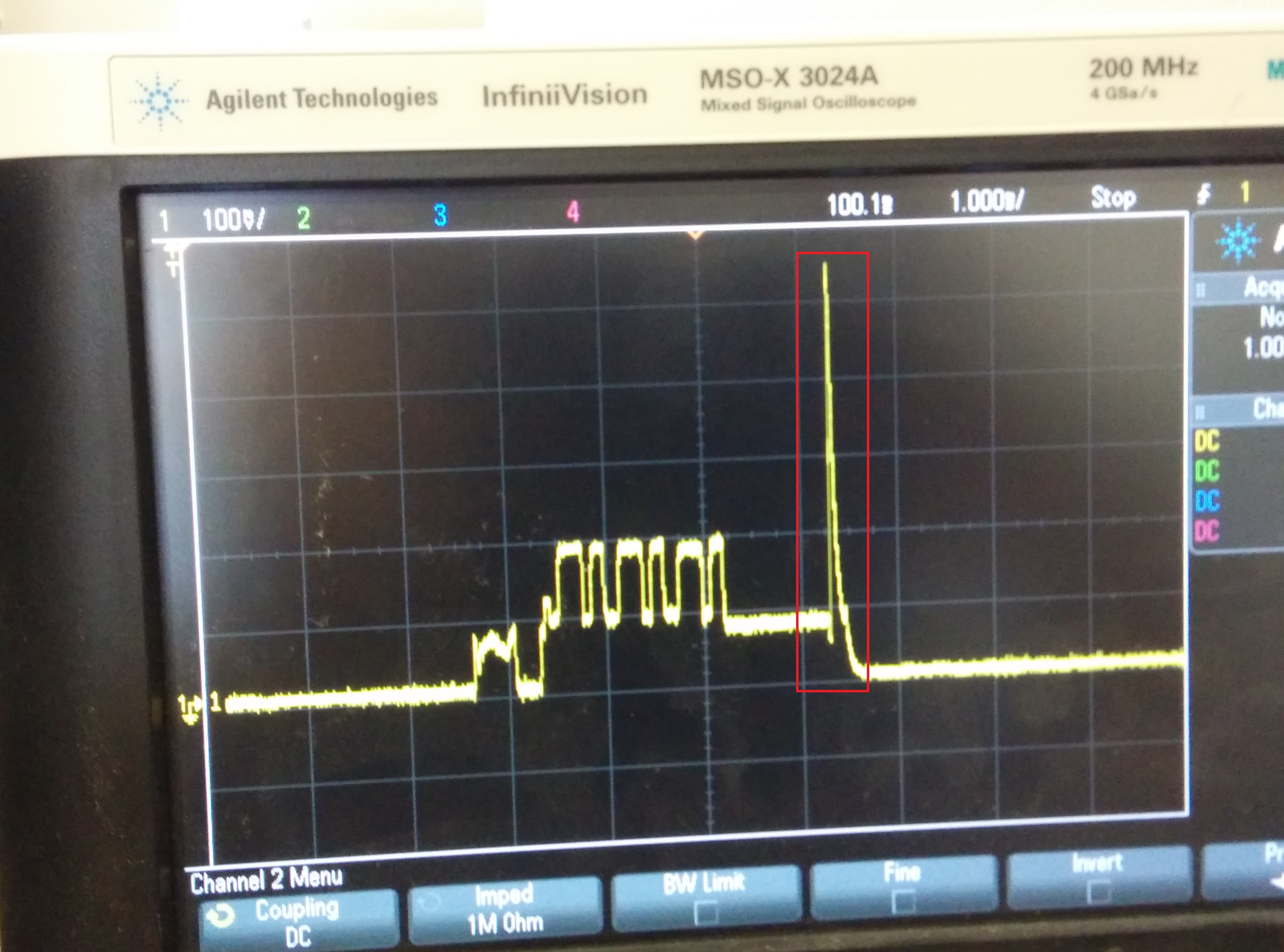
It shows this current consumption peak at the end of the adv packet with a maximum value of circa 55 mA (a 10 ohm resistor at the input is used, so the value read with the oscilloscope is divided by 10). Both my custom firmware and the raw provided Keyfob firmware present this behavior. This current peak occurs everytime that the CC2541 goes to sleep mode (PM2), so it also happens, for example, when a connection event is sent and when I check the battery level.

If I test, for instance, the also provided SimpleBLEPeripheral firmware, on the same board it shows an advertising packet like the one depicted below, which shows no peak like the one described above:

I know that the SimpleBLEPeripheral project features no connection services,  but is this difference something expected? A picture with both cases on the same window is show below:

Has anyone here encountered some similar behavior before?

Thank you all for your attention.

Best Regards,

Jose Sales

  • Hello Jose. What hardware is this on: SmartRFEM or Keyfob? Do you have any peripherals connected such as LED, button, buzzer, etc, that could be causing this?
  • Hi Jose,

    Since you have followed the keyfob design I assume you are using the TPS62730 regulator? If so, the current peak is caused by the regulator going into bypass mode when the CC2541 goes to PM2. When that happens the VDD net is switched from 2.1 V to your supply voltage (3.0 V?) and the current peak is caused by the charge-up of the decoupling caps.

    Cheers,
    Fredrik

  • Hi Fredrik,

    Thanks for the reply,

    Yes, I am using the TPS62730 regulator, with a 3.0V supply voltage. I think that probably explains the current peak. I will further investigate to check it. Do you suggest any tip to avoid that kind of current peak? I was also tricked to the fact that on the SimpleBLEPeripheral example project this does not occur.

    Best regards,
    Jose Sales
  • Hi Tim,

    Thanks for the reply,

    I am currently using the CC2541 Keyfob, but my main target is a custom PCB that I am developing. These measurements are made with the peripherals connected, although they are disabled. I was wondering if I need to take into account the leakage consumption of the peripherals would add a greater impact on the battery life, which is the most important feature of my application. As Friedrik suggested, this spike could happen due to TPS62730 bypass activity, but I will further check if that happens.

    Best regards,
    Jose Sales
  • Hi Jose,

    It is hard to avoid the current peak when you switch the supply voltage to the CC2541 (with its decoupling caps) from 2.1 to 3 V. If this is not acceptable in your application you can consider using the TPS62740 instead. That regulator does not switch to bypass in LPM due to the ability to maintaining high efficiency for uA loads. You will increase the sleep current by a couple of uA though.

    Best regards,
    Fredrik
  • Hi all,


    Jose's  colleague here. Our main concern is related to power consumption. Our proprietary board consumed half a CR2430 (290mAh) in about a week.

    Could those current peaks be the cause of it? We are not yet using the C7 (47uF) (See: AN092 - Page 8) capacitor for smoothing such peaks.

    The device is most of the time in connectable advertising mode. We measured sleep current with an ammeter to be around 2uA and the consumption profile while advertising a packet is as follows:  

      It seems ok except for the current peak while entering PM2 sleep mode.

    Any guess on what might likely be the cause of such an abnormal power consumption?

    Best regards,

    Gabriel

  • Hi Gabriel,

    The current peak is expected due to the regulator output switching from 2.1 V to the battery voltage (~3 V). I would recommend mounting the 47 uF cap.

    Best regards,
    Fredrik
  • Hi Fredrik,

    We will do that and test whether there are any reduction in overall power consumption or not.
    I insist on my previous question. The power consumption profile for both advertising and connection mode seems to be ok. In other words, the device is entering sleep mode. Do you believe those current peaks could be somehow reducing the battery life so dramatically?

    Best regards,
    Gabriel
  • Hi all, 

    We got an update. We have tested the exactly same firmware on a CC2540 MINI-DK and on a CC2541 MINI-DK. The CC2541 has drained the battery way faster than the CC2540, which contains no TPS meaning no current peaks. The CC2541 does have a 47uF cap mounted on it which is supposed to smooth those current peaks. Question: May it be that 47 uF is not enough? Please give us a feedback on that issue. We are suspicious that such current peaks are decreasing battery capacity. Have you ever heard of any other similar issue?

    Best regards,

    Gabriel 


  • Hi Gabriel,

    That is interesting results! To answer your last question first, we have not received any similar feedback before. However, I do agree that current peaks can be a killer for coin cell batteries.

    One thing you can do as a final confirmation is to run the same SW on the CC2541 keyfob, but with the DCDC regulator forced to bypass.

    If the current peaks turns out to be the problem, I would add more capacitance, as you suggest, maybe also with a small resistor between the battery and the cap. An alternative, as I recommended above, is to use the TPS62740 instead as this does not switch to bypass when the CC2541 goes to sleep.

    Best regards,
    Fredrik
  • Hi Fredrik,

    Thank you for your prompt reply. I will do the test you suggested bypassing the TPS62730. I am not sure our application allows us to use TPS62740 since it would increase current consumption while in sleep mode. We just mounted a 100 uF tantalum cap on the board and the peaks have considerably decreased. However, I have got two questions for you:

    1) Is there any drawback, expect for the cost, in adding such a large capacitor to the circuit?
    2) Would adding the extra resistor you mentioned add any significant power dissipation?

    Once again thanks,
    Gabriel