This thread has been locked.

If you have a related question, please click the "Ask a related question" button in the top right corner. The newly created question will be automatically linked to this question.

Custom cc2640 board: non-recoverable?

Other Parts Discussed in Thread: CC2640

Hi everyone,

I was using our custom board with CCS 6.1.0, developing and running program without problems. At any given time the board stopped responding normally: when I run the program, launching a debug session, there is no error in CCS. It says that program is running in my board, but this is not true.

Then I try to recover board using SmartRF Flash Programmer 2 v1.6.0, but the process fails. Afterwards, when trying to read flash I get the following error messages:

>Initiate access to target: XDS-FTVDGEJYA.

>Failed to read target memory.

>Error while reading memory range. Address 0x40091090.

>Start reading flash...

>Unable to halt target CPU

>Reset target ...

>Reset of target successfull.

I have found this thread https://e2e.ti.com/support/wireless_connectivity/f/538/p/417409/1500948 where svendbt concludes that that board was non-recoverable, after user writes 0's on CCFG. In my case, I was using only CCS to flash always the same program, and I think I do not write zeros, however the log messages are identical.

Is there anyway I can recover my board (or, at least confirm that there is nothing to do)?

Thank you very much.

  • Hello,

    I'll let svendbt comment further, but can you confirm if you did the force mass erase option in FP2?

    Best wishes
  • Hi JXS,
    Thank you for your interest. Indeed, I did that unbrick process several times, but with same results.
    Regards.
  • Is you board recognized by SmartRF Flash Programmer 2? If so it should be fully recoverable and debugging should also work as usual.

    • Are all needed signals connected? (TCK,TMS, RESET_N, VDD, GND)?
      • The debugger will do a pin reset and halt the CPU to ensure that SW will not power off JTAG (done by RTOS power driver) before attaching
    • Can you try to do a forced erase in SRF Prog 2 (click Wrench in upper right corner)

    Regards,
    Svend

  • Hi svendbt, JXS and everybody,

    This issue has become a blocking problem for our development, since, at this time, all our board units are in this unrecoverable (by us) state. Next, I revise and summarize our situation in detail:

    • We are developing using our custom board based on CC2640 QFN32/5x5 MCU.
    • We are using CCS 6.1, SmartRF Flash Programmer 2 v1.6.1 and XDS100v3 debugger.
    • We are developing an application to communicate MCU and SPI and I2C peripherals (PMU, accelerometer...) that are included in our design.
    • We have enabled UIA and we are using LoggerTyp_STOPMODE, using HW breakpoints to check debug messages (this issue is one of our main suspicious now about what is causing the problem).
    • When running our code from CCS, we had observed that most of times after a debug session, when launched another one, this last session was not "real": CCS does not throw any error message, and it says that code is running on our board, but execution does not stop at breakpoints, also there is not log messages etc. In this situation, the only way we had found to recover the normal behaviour wast to load a complete flash image we used as backup using SmartRF FP2 (we found that restarting board did not solve the issue).
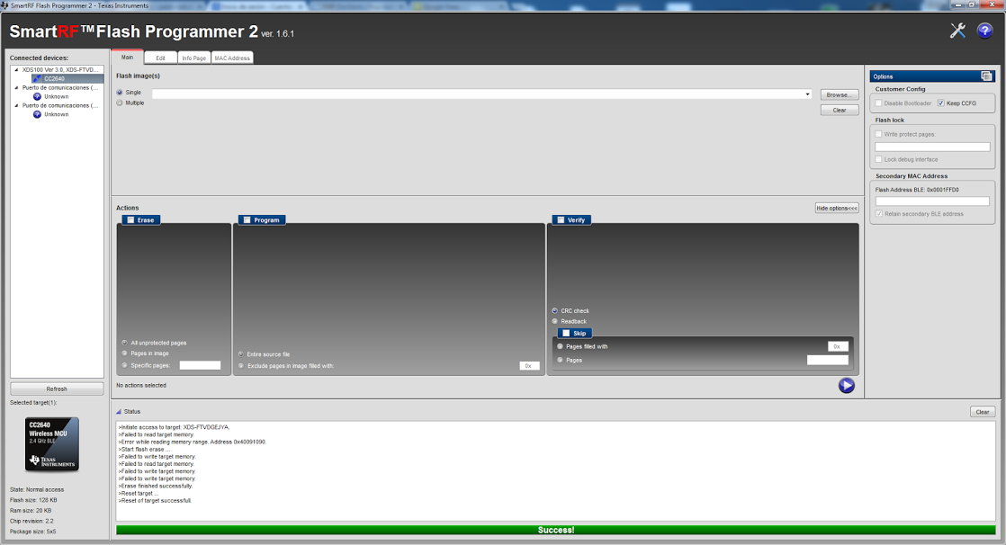
    • After some iterations repeating the steps indicated in the previous point, we found that we can not load the flash image, also we can not read or write in the internal flash. Trying to recover board using "Forced Mass Erase Option" gives a similar error message, as seen in following screen capture:

    • We have checked JTAG signals, using a logical analyzer and the software "Saleae Logic 1.1.34 Beta". We have captured signals when trying "Forced Mass Erase Option" to get the following:  I would be happy if you could take a look over it. If you prefer another format for the capture file, please make me know and I generate it.

    We can do any test you suggest, and send or comment results. At this time, this issue is blocking all our development, so any advice or suggestion is welcome.

    Thank you very much.

  • The logging feature uses a lot of RAM so you easily end up with some stack overflows but you should be able to erase the device still.

    Can you verify that the reset signal connected all the way to the chip? When uploading flash to the device the debuggers resets the device and then toggles TCK to make the boot ROM stop the CPU before TI RTOS starts up and disables JTAG again.

    To exclude either the SW or the board it would be great if you can test with our SimpleBLEPeripheral example. Remove TI_DRIVERS_LCD_INCLUDED as compiler preprocessor and change the BoardGpioInit table in the Board file to match your setup.

    Regards,
    Svend
  • We also have an example of a much more non-intrusive logging method available if you don't need real-time logging:
    processors.wiki.ti.com/.../CC26xx_Adding_basic_printf_over_uart_with_TI-RTOS
  • Hi svendbt,
    In effect, we were previously using SimpleBLEPeripheral for a long time, and also debugging with UART (in fact, we have the code still active to use it). However, our main problem right now is to be able to recover any of the boards from their current state!!. If not, we don't have hardware to continue.
    Any suggestions?
    Thank you very much
  • Could you post your schematic? There are a few reasons I could think of causing this.

    - RESET_N is actually not connected between the debugger and the chip
    - Supply and regulated voltages are incorrect.
    - Program code causing high IO current (from e.g. shorting an IO) resulting in a device reset. Should still be recoverable though.

    Regards,
    Svend
  • Hi Svend,
    I think we have finally found what was causing this problem: usage of HW breakpoints in CCS and stopping a debug session while CPU is stopped in a HW breakpoint. We start to use HW breakpoints as a way to debug using our XDS100v3 and LoggerType_STOPMODE.

    We have found, that doing this, internal flash is not accessible for SmartRF FP2 (even when we had closed CCS before). Also, we have found that the only way to recover our boards is to launch from CCS a program with no breakpoints at all.

    So, after discovering this, I would like to know two issues:

    1. Do you think that stopping execution in a HW breakpoint is a plausible justification for the behaviour we have found, or maybe there is something more that we are not understanding?

    2. Should we manage without this type of breakpoints? or even without using JTAG to debug, and using only UART?. Maybe is there another logging type or another breakpoint type that should cause less problems, or should we understand better how to use what we are using know?. Any suggestions you can make are welcome.

    Thank you very much,
    Regards.
    José Antonio Martínez
  • Hi José,

    CCS (or IAR for that sake) insert HW breakpoints by using the M3's Flash Patch and Breakpoint Unit (FPB) when you set breakpoints in your code through CCS. Do you override these somehow by the code you have in the device?

    Stopping the CPU at a HW breakpoint should -not- cause the device to be inaccessible from SmartRF Flash Programmer 2.
    The way both CCS/SRF Prog2 / IAR does a flash program/erase of the device and starts a debugging session is:

    - Toggle the RESET_N pin causing a full device reset
    - Toggle TCK a number of times
    - ROM bootloader detects TCK is toggled (halt-in-boot signal) and stops program execution before any code from flash has run
    - Uploads a flash loader to RAM through JTAG
    - Writes / erases flash through the flash loader
    - Moves program counter to start of flash and starts executing.

    As long as you are using chip revisions 2.X this should work fine when RESET_N is connected to your board they should be fully accessible again every time you start debugging or do a flash erase with SRF Prog 2.

    Regards,
    Svend
  • Can you verify that the reset signal connected all the way to the chip? When uploading flash to the device the debuggers resets the device and then toggles TCK to make the boot ROM stop the CPU before TI RTOS starts up and disables JTAG again.
  • Hi Svend,

    Sorry for the long delay answering. We have been very confused about this behaviour, trying to investigate its causes. I would like to resume the issue based only in the basical facts we have confirmed. These are the steps 100% reproducible:

    1. We take our custom HW and make a Forced Mass Erase with SmartRF FP2 v1.6.1
    2. We run SimpleBLEPeripheralStack (from CCS 6.1).
    3. We stop execution and run SimpleBLEPeripheral (from CCS 6.1): execution is OK
    4. We stop and relaunch execution of SimpleBLEPeripheral (from CCS 6.1): now execution fails. CCS does not give any error or advertising, but board is not advertising by bluetooth (also we see that execution does not stop at init of main as in step 3 does).

    The only modifications in SimpleBLEPeripheral, as you suggested, are to remove TI_DRIVERS_LCD_INCLUDED as compiler preprocessor and change the BoardGpioInit table (we comment all lines except "PIN_TERMINATE"). Now, we don't use JTAG logging nor breakpoints.

    This behaviour is 100% reproducible also with our program (based on TimeApp): execution only works firs time is launched after restoring board with Forced Mass Erase. Our HW team says that RESET signal is OK and that board is restarting when launching our program, but they can not share our schematic (confidential reasons).

    Any clues or suggestions?

    Thank you very much.