This thread has been locked.

If you have a related question, please click the "Ask a related question" button in the top right corner. The newly created question will be automatically linked to this question.

CC2640 - LF clock is not working

Other Parts Discussed in Thread: CC2640, CC2650

Hi everyone,

I come back on this problem because I really need to find the solution ! 

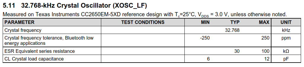
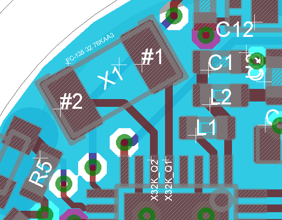
I use an external 32.768 crystal (FC-135) connected to X32K_Q1 and Q2 pins as on the picture. There is no capacitor next to it because I don't have much place (and it is already +- 20ppm, far enough). The CC2640 I use is 4x4mm (complete name : CC2640F128RSMT) version 2.2

I'm using the latest version of TI-RTOS, driverlib and XdcTools. Configuration of clocks and timers is:

/* Enable idle task (default). */
Task.enableIdleTask = true;
/* Clock options */
Clock.tickPeriod = 10;
Clock.timerId = -1;
Power.idle = true;
Power.policyFunc = Power.standbyPolicy;
Clock.tickSource = Clock.TickSource_TIMER;
Task.idleTaskStackSize = 512;
Task.idleTaskVitalTaskFlag = false;

In the ccfg.c file, the configuration is the following:

//#####################################
// Clock settings
//#####################################

//#define SET_CCFG_MODE_CONF_SCLK_LF_OPTION            0x0        	// LF clock derived from High Frequency XOSC
//#define SET_CCFG_MODE_CONF_SCLK_LF_OPTION            0x1        	// External LF clock
#define SET_CCFG_MODE_CONF_SCLK_LF_OPTION              0x2      	// LF XOSC
//#define SET_CCFG_MODE_CONF_SCLK_LF_OPTION            0x3        	// LF RCOSC

// #define SET_CCFG_MODE_CONF_XOSC_CAP_MOD              0x0        // Apply cap-array delta
#define SET_CCFG_MODE_CONF_XOSC_CAP_MOD                 0x1        // Don't apply cap-array delta 

#define SET_CCFG_MODE_CONF_XOSC_CAPARRAY_DELTA          0xFF       // Signed 8-bit value, directly modifying trimmed XOSC cap-array value

#define SET_CCFG_EXT_LF_CLK_DIO                         0x01       // DIO number if using external LF clock

#define SET_CCFG_EXT_LF_CLK_RTC_INCREMENT               0x800000   // RTC increment representing the external LF clock frequency

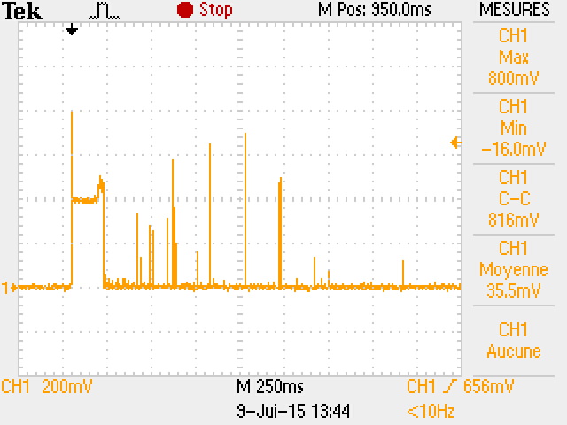
The problem is that the system does not go in standby mode and I have an offset of 1.5mA in Idle mode (picture is showing the current consumption during advertising, around 1.3mA/division. 

I decided to check the configuration during the main function of the task by using the LED on my board : 

	const uint16_t Wait_ = 50000 ;
	OSCClockSourceSet(OSC_SRC_CLK_LF, OSC_XOSC_LF);
	if(OSCClockSourceGet(OSC_SRC_CLK_LF) != OSC_XOSC_LF)
	{
		if(PIN_open(&hStateHui, aPinListHui))
		{
			PIN_setPortOutputValue(&hStateHui, (1<<LED1));
			Task_sleep(Wait_);
			PIN_setPortOutputEnable(&hStateHui, 0);
			Task_sleep(Wait_);
			PIN_close(&hStateHui);
		}
	}

	if(OSCClockSourceGet(OSC_SRC_CLK_HF) != OSC_XOSC_HF)
	{
		if(PIN_open(&hStateHui, aPinListHui))
		{
			PIN_setPortOutputValue(&hStateHui, (1<<LED1));
			Task_sleep(Wait_);
			PIN_setPortOutputEnable(&hStateHui, 0);
			Task_sleep(Wait_);
			PIN_close(&hStateHui);
		}
	}

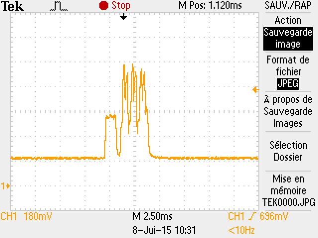
The led will blink only one time, when I check if the source of LF CLK is incorrect. I measured the signal on X32K_Q2 pin and I saw a 32.68Khz sinus (+-46mV) with an offset of 350mV. This signal does not change during measures and the voltage on DCOUPL pin is stable at 1.35V.

I have tested 4 PCBs in the very same configuration, but none of them is able to go in standby mode by using the crystal. It works by setting it to internal RCOSC but the errata file concerning the CC26xx series indicate the it cannot be trusted, and sometimes during my tests i saw the system restarting before advertising (very bad for the global current consumption). In last topic somebody said that using external CLK on a pin is working, but I can't use this configuration.

Thanks in advance to anybody able to help me, i really need to find a solution or a reason of this failure.

Have a nice day

Sebastien

  • I tried this morning with another 32.768khz crystal (Micro Crystal CM7V-T1A) with a temperature wave for soldering going less high and shorter.. and the problem is still here. I will try with a CC2650 next week to see if the problem is coming from the CC2640 only.

    But maybe it's still a configuration problem in my project or something like that ?
  • The 32 kHz oscillator will not work without external crystals. The minimum crystal load cap for the 32 kHz crystal is 6 pF.

    Cheers,
    Fredrik
  • And you should not have signal traces underneath the RF circuitry btw.
  • Why the oscillator couldn't work without crystals ? The 24Mhz don't have problems without them... is it proper to low frequency crystals ?
    I will really have no choices about lines under RF circuitry if i have to add two capacitors next to the crystal :(
  • That is because the 24 MHz oscillator pins have internal load caps on the chip.
  • Ok so now the standby current is ok (I put two 12pf capacitors), but the system is restarting before advertising, every time:

  • Can you post your schematic and complete layout?

  • Hi everyone,

    On the CC2640 datasheet, there is a this specification about 32.768khz clock :

    It indicates that Crystal load capacitance has to be between 6 and 12pF. The official FC-135 is 7pF and mine was 12.5pF (FC-135 KA-A3 and not KA-AG...), and even with capacitors next to him (not needed to work with on a msp430 btw..), it will lead to a imprecise behavior.

    So for everyone using a CC2640/CC2650 : The LF XOSC chip must be between 6-12pf and must have 2 capacitors next to him. 

    Something else I founded in power settings (ccfg.c file) : 

    //#####################################
    // Power settings
    //#####################################
    //#define SET_CCFG_MODE_CONF_VDDR_CAP                   0x34       // Unsigned 8-bit integer representing the min. decoupling capacitance on VDDR in units of 100nF
    #define SET_CCFG_MODE_CONF_VDDR_CAP                     0x01       // Unsigned 8-bit integer representing the min. decoupling capacitance on VDDR in units of 100nF
    

    The minimal decoupling capacitance in units of 100nF was set to 0x34 (???), and some restarts were directly caused by this configuration ! I use 100nF capacitors on my design (minimal value), so I set it to 0x01 and everything is working now...

    Have a nice day

    Sebastien

  • Pittet Sebastien said:

    It indicates that Crystal load capacitance has to be between 6 and 12pF. The official FC-135 is 7pF and mine was 12.5pF (FC-135 KA-A3 and not KA-AG...), and even with capacitors next to him (not needed to work with on a msp430 btw..), it will lead to a imprecise behavior.

    So for everyone using a CC2640/CC2650 : The LF XOSC chip must be between 6-12pf and must have 2 capacitors next to him. 

    This is how any crystal oscillator is designed, the crystal requires a certain amount of load capacitance to work. In the case of the CC26xx the load capacitance must be in the range 6 - 12 pF. With properly sized capacitors the 32 kHz oscillator will work perfectly. If you see imprecise behaviour this can be caused by a number of HW design issues. Please ellaborate on what problems you are seeing. I would also very much like to see the spec of the MSP430 part you are referring to that works without capacitors.

    Pittet Sebastien said:

    Something else I founded in power settings (ccfg.c file) : 

    //#####################################
    // Power settings
    //#####################################
    //#define SET_CCFG_MODE_CONF_VDDR_CAP                   0x34       // Unsigned 8-bit integer representing the min. decoupling capacitance on VDDR in units of 100nF
    #define SET_CCFG_MODE_CONF_VDDR_CAP                     0x01       // Unsigned 8-bit integer representing the min. decoupling capacitance on VDDR in units of 100nF
    

    The minimal decoupling capacitance in units of 100nF was set to 0x34 (???), and some restarts were directly caused by this configuration ! I use 100nF capacitors on my design (minimal value), so I set it to 0x01 and everything is working now...

    This value should be the total capacitive load on VDDR. If you are following the reference design this is 100nF + 100nF + 10uF = 10.2 uF. Additionally you must derate for DC-bias and temperature (check the capacitor datasheets). The default value is thus 0x34 x 100 nF = 5.2 uF.


    This value is used when calculating the initial recharge algorithm when going to Standby mode. Using a lower value than necessary (such as 0x01 will give excessive current consumption.

    Cheers,
    Fredrik