


Hi Everyone,
I am interfacing M95M02 EEPROM with CC2541 using SPI in USART1. I am able to see the proper clk and MOSI signal as per settings but in MISO,there is no any signal.Before reading the data i am writing EEPROM with PIC microcontroller and verified it.the data are written properly. while reading with CC2541 on same location i am unable to get data.
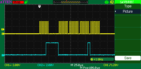
Write and read location is 0x0001,CH1 - Clk signal,CH2 - MOSI.
If there is any problem with code please intimate me.Thanks in advance
here my code,
#include <hal_types.h>
#include <hal_wait.h>
#include <main.h>
// Include Name definitions of individual bits and bit-fields in the CC254x device registers.
#include <ioCC254x_bitdef.h>
#include "ioCC2541.h"
#define CS P1_4
// These values will give a baud rate of approx. 2.00 Mbps at 32 MHz system clock.
#define SPI_BAUD_M 0
#define SPI_BAUD_E 13
#define ins_wr_en 0x06
#define ins_wr_dis 0x04
#define ins_wr 0x02
#define ins_rd 0x03
#define ins_rd_stat 0x05
#define ins_wr_stat 0x01
/***********************************************************************************
* LOCAL VARIABLES
*/
// Define size of buffer and number of bytes to send
#define BUFFER_SIZE 252
// Masters's transmit buffer
static uint8 txBufferMaster[BUFFER_SIZE];
static uint8 eeprom_read_val;
/***********************************************************************************
* LOCAL VARIABLES
*/
static uint16 adc_result;
/***********************************************************************************
* CONSTANTS
*/
void initialise(void)
{
// Set system clock source to HS XOSC, with no pre-scaling.
CLKCONCMD = (CLKCONCMD & ~(CLKCON_OSC | CLKCON_CLKSPD)) | CLKCON_CLKSPD_32M;
// Wait until clock source has changed.
while (CLKCONSTA & CLKCON_OSC);
// Configure USART0 for Alternative 1 => Port P0 (PERCFG.U0CFG = 0).
PERCFG = (PERCFG & ~PERCFG_U0CFG) | PERCFG_U0CFG_ALT1;
PERCFG = (PERCFG & ~PERCFG_U1CFG) | 0x02; //Assigning USART1 module to Alt2 location
// Give priority to USART 0 over Timer 1 for port 0 pins.
P2DIR &= P2DIR_PRIP0_USART0;
P2SEL &= 0x40; //Setting Priority for USART1
// Set pins 2, 3 and 5 as peripheral I/O and pin 4 as GPIO output.
P0SEL |= (BIT7 | BIT3 | BIT2); //Assigning P0.7 to ADC and 2/3 to UART peripheral
P1SEL |= (BIT7 | BIT6 | BIT5); //Assigning P1.7/6/5/4 to SPI peripheral
P1SEL &= ~BIT4;
P1DIR |= BIT4; //Assigning BIT4 as GPIO for Slave Select
P1_4 = 1;
// Initialize P0_0 for LED.
P0SEL &= ~BIT0; // Function as General Purpose I/O.
P0DIR |= BIT0; // output.
P0_0 = 1; //Turn Off
}
#pragma vector = T3_VECTOR
__interrupt void t3_isr(void)
{
// Clears the module interrupt flag.
T3OVFIF = 0;
// Toggles LED1 on SmartRF05EB or CC2544Dongle.
// P0_0 ^= 1; // Toggle SRF05EB LED1.
// Clears the CPU interrupt flag.
T3IF = 0;
}
void main (void)
{
initialise();
adc_config();
config_uart0();
// interrupt_config();
timer_config();
spi_config();
while(1)
{
uart0_byte_out(read_ext_eeprom(0x0001));
halMcuWaitMs(1000);
}
}
/***********************************************************************************
* LOCAL FUNCTIONS
*/
void led(void)
{
P0_0 = 0;
halMcuWaitMs(200);
P0_0 = 1;
}
void adc_config(void)
{
// Set [APCFG.APCFG0 = 1].
APCFG = 0x80;
// Set [ADCCON1.STSEL] according to ADC configuration.
ADCCON1 = (ADCCON1 & ~ADCCON1_STSEL) | ADCCON1_STSEL_ST;
// Set [ADCCON2.SREF/SDIV/SCH] according to ADC configuration.
ADCCON2 = ADCCON2_SREF_AVDD | ADCCON2_SDIV_128 | ADCCON2_SCH_AIN7;
}
uint16 adc_convert(void)
{
// Set [ADCCON1.ST] and await completion (ADCCON1.EOC = 1).
ADCCON1 |= ADCCON1_ST;
while( !(ADCCON1 & ADCCON1_EOC));
adc_result = (ADCL >> 4);
adc_result |= (ADCH << 4);
return adc_result;
}
void interrupt_config(void)
{
//EA = 1; //Enables global interrupts (IEN0.EA = 1)
//T3IE = 1; //interrupts from Timer 3
}
void timer_config(void)
{
T3CC0 = 124;
T3CCTL0 = 0x44;//T3CCTLn_IM | T3CCTLn_MODE;
T3CTL = T3CTL_DIV_16 | T3CTL_MODE_MODULO | T3CTL_CLR | T3CTL_START;
}
void spi_config(void)
{
U1CSR = 0x00;//~(0x82); //Mode - SPI; Slave - Master
U1BAUD = SPI_BAUD_M;
U1GCR = (U1GCR & ~(0xFF)) | SPI_BAUD_E;
U1GCR |= 0x20;
}
void spi_send(uint8 spi_data)
{
CS = 0;
U1DBUF = spi_data;
while(!(U1CSR & 0x02)); //wait here upto the byte transmission
U1CSR &= ~0x02; //Clearing byte transimitted status for sensing next transmission
CS = 1;
}
uint8 spi_read(void)
{
uint8 read_data = 0;
CS = 0;
U1DBUF = 0x00; //loading dummy data in buffer
while(!(U1CSR & 0x02)); //wait here upto the byte transmission
U1CSR &= ~0x02; //Clearing byte transimitted status for sensing next transmission
read_data = U1DBUF; //Get data from slave
CS = 1;
return read_data;
}
void write_enable()
{
CS = 0;
spi_send(ins_wr_en);
CS = 1;
}
void write_disable()
{
CS = 0;
spi_send(ins_wr_dis);
CS = 1;
}
void write_ext_eeprom(unsigned long int address, unsigned char data)
{
write_enable();
del_ms(15);
CS = 0;
spi_send(ins_wr);
spi_send(address>>16);
spi_send(address>>8);
spi_send(address);
spi_send(data);
CS = 1;
}
unsigned char read_ext_eeprom(unsigned long int address)
{
CS = 0;
spi_send(ins_rd);
spi_send(address>>16);
spi_send(address>>8);
spi_send(address);
eeprom_read_val = spi_read(); // release the bus
CS = 1;
return(eeprom_read_val);
}
void uart0_byte_out(uint8 out_data)
{
// Clear any pending TX interrupt request (set U0CSR.TX_BYTE = 0).
U0CSR &= ~U0CSR_TX_BYTE;
U0DBUF = out_data;
while(! (U0CSR & U0CSR_TX_BYTE) );
}
