


Hello All,
I have been working with the Tiva C launchpad, attempting to get the Tiva C - SPPDemo (NoOS) running on the CC256xQFN-EM. To do this I have the EM Adapter Boosterpack. I have populated the 32K slow clock - PN: ASVK-32.768KHZ-LJT
I have followed the process to create a new workspace and imported the SPPDemo project making the following changes:
Changed the build to be for DK-TM4C123G: PN_TM4C123GH6PM
I have altered the following in files:
BTPSVEND.C:
Added :
#define __SUPPORT_CC256XB_PATCH__
HALCFG.h
  /* Here is the default allocation of pins to connect to the Bluetooth*/
   /* device, using UART1.                                              */
   /*                                                                   */
   /* Function     Port/Pin                                             */
   /* --------     --------                                             */
   /*   RX           oldPC4 newPB0                                      */
   /*   TX           oldPC5 newPB1                                      */
   /*   RTS          oldPF0 newPC4                                      */
   /*   CTS          oldPF1 newPC5                                      */
   /*  RESET         oldPF2 newPA7                                      */
   /*                                                                   */

   /* Define the UART peripheral that is used for the Bluetooth         */
   /* interface.                                                        */
   /* * NOTE * At this time, only UART1 can be used because it supports */
   /*          hardware flow control.                                   */
#define HCI_UART_BASE                                    UART1_BASE
#define HCI_UART_INT                                      INT_UART1
#define HCI_UART_PERIPH                         SYSCTL_PERIPH_UART1


   /* Define the GPIO ports and pins that are used for the UART RX/TX   */
   /* signals.                                                          */
   /* * NOTE * See gpio.h for possible values for HCI_PIN_CONFIGURE_    */
   /*          macros.                                                  */

//#define HCI_UART_GPIO_PERIPH                    SYSCTL_PERIPH_GPIOC
//#define HCI_UART_GPIO_BASE                          GPIO_PORTC_BASE
//#define HCI_UART_PIN_RX                                  GPIO_PIN_4
//#define HCI_UART_PIN_TX                                  GPIO_PIN_5
//#define HCI_PIN_CONFIGURE_UART_RX                     GPIO_PC4_U1RX
//#define HCI_PIN_CONFIGURE_UART_TX                     GPIO_PC5_U1TX


#define HCI_UART_GPIO_PERIPH                    SYSCTL_PERIPH_GPIOB
#define HCI_UART_GPIO_BASE                          GPIO_PORTB_BASE
#define HCI_UART_PIN_RX                                  GPIO_PIN_0
#define HCI_UART_PIN_TX                                  GPIO_PIN_1
#define HCI_PIN_CONFIGURE_UART_RX                     GPIO_PB0_U1RX
#define HCI_PIN_CONFIGURE_UART_TX                     GPIO_PB1_U1TX


   /* Define the GPIO ports and pins that are used for the UART RTS     */
   /* signal.                                                           */
//#define HCI_UART_RTS_GPIO_PERIPH                SYSCTL_PERIPH_GPIOF
//#define HCI_UART_RTS_GPIO_BASE                      GPIO_PORTF_BASE
//#define HCI_UART_PIN_RTS                                 GPIO_PIN_0
//#define HCI_PIN_CONFIGURE_UART_RTS                   GPIO_PF0_U1RTS

#define HCI_UART_RTS_GPIO_PERIPH                SYSCTL_PERIPH_GPIOC
#define HCI_UART_RTS_GPIO_BASE                      GPIO_PORTC_BASE
#define HCI_UART_PIN_RTS                                 GPIO_PIN_4
#define HCI_PIN_CONFIGURE_UART_RTS                   GPIO_PC4_U1RTS


   /* Define the GPIO ports and pins that are used for the UART CTS     */
   /* signal.                                                           */
//#define HCI_UART_CTS_GPIO_PERIPH                SYSCTL_PERIPH_GPIOF
//#define HCI_UART_CTS_GPIO_BASE                      GPIO_PORTF_BASE
//#define HCI_UART_PIN_CTS                                 GPIO_PIN_1
//#define HCI_PIN_CONFIGURE_UART_CTS                   GPIO_PF1_U1CTS


#define HCI_UART_CTS_GPIO_PERIPH                SYSCTL_PERIPH_GPIOC
#define HCI_UART_CTS_GPIO_BASE                      GPIO_PORTC_BASE
#define HCI_UART_PIN_CTS                                 GPIO_PIN_5
#define HCI_PIN_CONFIGURE_UART_CTS                   GPIO_PC5_U1CTS

    /* Define the GPIO ports and pins that are used for the Bluetooth    */
   /* RESET signal.                                                     */
//#define HCI_RESET_PERIPH                        SYSCTL_PERIPH_GPIOF
//#define HCI_RESET_BASE                              GPIO_PORTF_BASE
//#define HCI_RESET_PIN                                    GPIO_PIN_2


#define HCI_RESET_PERIPH                        SYSCTL_PERIPH_GPIOA
#define HCI_RESET_BASE                              GPIO_PORTA_BASE
#define HCI_RESET_PIN                                    GPIO_PIN_7

 #endif
I also Altered the LED signal pin in HALCFG.c for PF2
The project compiles fine (with 4 warnings).
The output on Hyper term is:
OpenStack().
Stack Init Failed: -4.
Unable to open the stack.
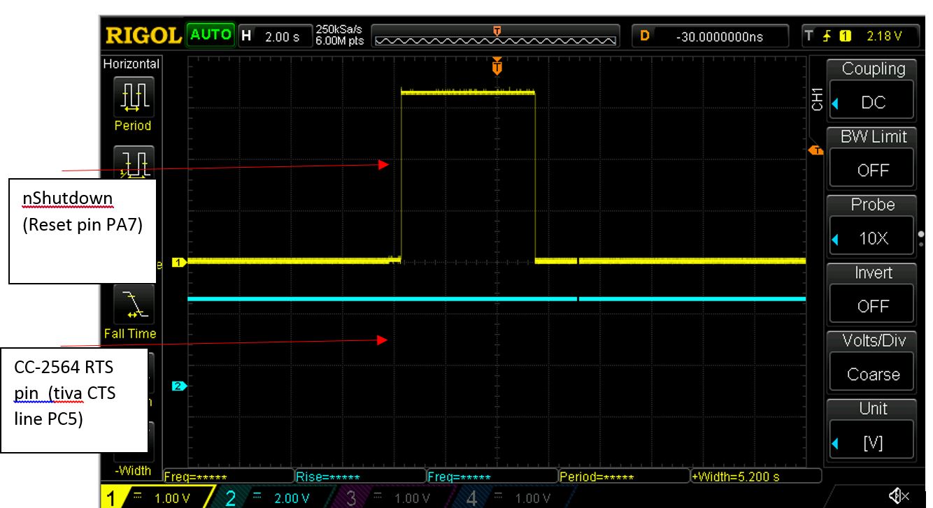
As you can see the nShutdown/Reset occurs but the HCI_RTS does not go low:
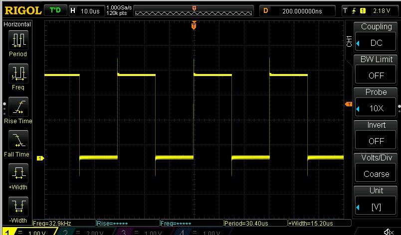
SloCLK signal, not sure if the is an issue because of ripple on the clock edges:
I have spend ample time going through an checking everything and researching others posts but seem to be at a roadblock here.
Can someone please provide some guidance here.
