


Hi Experts,
I bought a CC2540DK (SmartRF05EB 1.8.1 and a CC2540EM) and trying to verify that I can get to the GPIO. I have in past done a lot of arduino programming and I am trying to apply that knowledge to this board and failing miserably. Trying to get the CC2540 pin mapping to the GPIO headers is pretty complex but I think I have kinda got it. Here is what I mapped by going through the CC2540 chip reference, CC2540EM layout reference and finally SmartRF05 reference. I am a bit unsure if I got it completely right since P10 and P1 headers have some pins that are duplicated e.g. LCD_CS or SCLK, which confuses me on whether jumpers need to be removed on P10 or P1 or both?
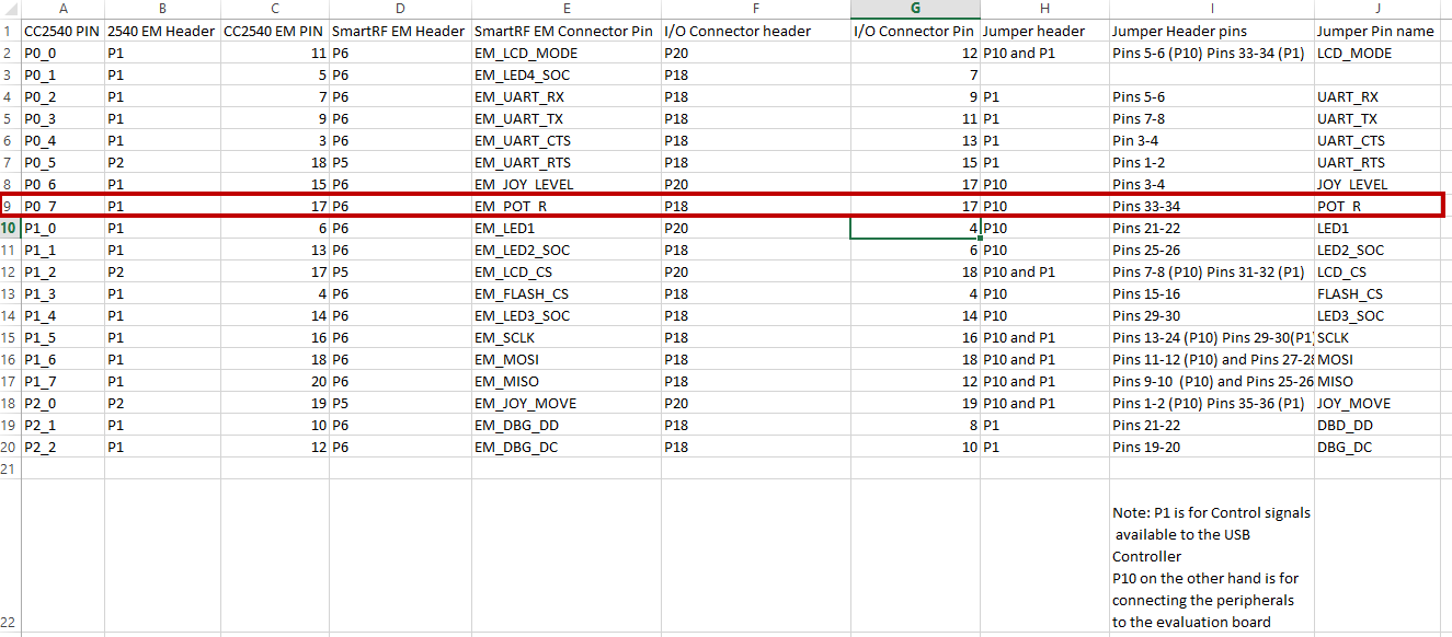
Anyways, moving forward, if I had to explain the following mapping table, I would say pin P0_7 on the CC2540 maps to Pin 17 on the CC2540EM which maps to the P6 connector on SmartRF which connects to P18 header on Pin 17. To make this pin accessible from the EM board and use it as a GPIO, I would have to take out the jumper on Pins 33-34 on pin header P10.
I did exactly this. and connected the positive terminal of a generic LED to this terminal. I connected the ground to the Pin 20 on header P20. I chose this pin because per the SmartRF and CC2540 manuals, this pin can supply up to 20mA of current which is needed to light up a small generic LED.
After that, I opened the simpleBLEPeripheral sample program in IAR embedded workbench and added the following code in config to configure pin P0_7 to be in OUTPUT mode
P0SEL = 0; // Configure Port 0 as GPIO
P1SEL = 0; // Configure Port 1 as GPIO
P2SEL = 0; // Configure Port 2 as GPIO
P0DIR = 0xFF; // Configure everything is an output pin
// all others (P0.2-P0.7) as output
P1DIR = 0xFF; // All port 1 pins (P1.0-P1.7) as output
P2DIR = 0x1F; // All port 1 pins (P2.0-P2.4) as output
P0 = 0x00; // All pins on port 0 to low except for P0.0 and P0.1 (buttons)
P1 = 0xFF; // All pins on port 1 to low
P2 = 0xFF; // All pins on port 2 to low
Finally, I modified the simpleProfileChangeCB like the following. Essentially, when the value 0x01 is received, I am turning the GPIO pin P0_7 ON and on receiving 0x02, I am switching it off. At least that is what I understand. And of course, I have taken the jumper 33-34 on P10 off to make the EM access the GPIO headers directly.
IAR connects to the board just fine. Additionally, I can successfully connect from my Bluetooth iPhone app and send values 0x01 and 0x02 to the board. The LCD shows the values it received. However, the LED does not switch on... I am quite lost on how to proceed or where I am going wrong.
See code below.
static void simpleProfileChangeCB( uint8 paramID )
{
uint8 newValue;
switch( paramID )
{
case SIMPLEPROFILE_CHAR1:
SimpleProfile_GetParameter( SIMPLEPROFILE_CHAR1, &newValue );
if(newValue==0x01)
{
P0_7= 0x1;
HalLcdWriteString( "value: 0x01", HAL_LCD_LINE_3 );
}
else if(newValue == 0x02)
{
P0_7= 0x0;
HalLcdWriteString( "value: 0x02", HAL_LCD_LINE_3 );
}
break;
}
}
Any help will be greatly appreciated.
Thanks
Sanjeev

