Hi everyone,
I have to manage a step-by-step motor in my project, and i measure the current through it to determine if the steps are a success or not. Four I/O are used with the sensor manager :
DIO 5 - ADC input for positive wave
DIO 7 - Digital output for positive wave
DIO 8 - ADC input for negative wave
DIO 9 - Digital output for negative wave
Theses I/O are not used by the main software (initialized pulled-down, input for adc and output for DIO7/DIO9)
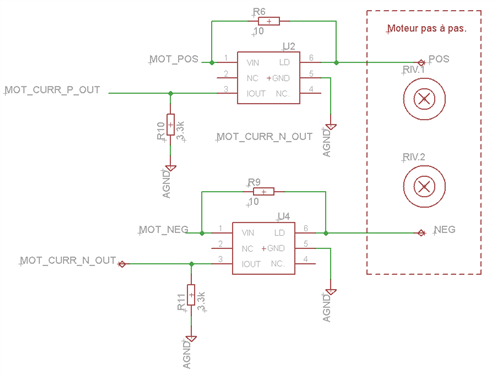
The current is sensed through a 10 ohm resistor and amplified with a FAN4010IL6X from Fairchild semiconductor. Output resistor is 3.3kOhm. Here is the schematic : MOT_POS and MOT_NEG are the digital input/outputs.
The functions used to start and stop the sensor controller :
/* Initialize the Sensor Controller  */
SCIF_RESULT_T SensorController_init()
{
        scifOsalEnableAuxDomainAccess();					// Prevent AUX from powering down
	scifOsalInit();											// Initializes the OSAL
	scifOsalRegisterTaskAlertCallback(scTaskAlertCallback);	// Register callback method for Task alert
	return scifInit(&scifDriverSetup);						// Enable the driver
}

 /* Start one time init-execute-terminate session  */
SCIF_RESULT_T SensorController_start_once()
{
	scifStartRtcTicksNow(0x00000100);	// Start ticks (for alert events)
    // Open the AUX I/O latches, which have undefined value after power-up. AUX_AIODIO will by default
    // drive '0' on all I/O pins, so AUX_AIODIO must be configured before IOC
    HWREG(AUX_WUC_BASE + AUX_WUC_O_AUXIOLATCH) = AUX_WUC_AUXIOLATCH_EN_TRANSP;
	scifTaskResourceInit();		  									// Start I/O
	return scifCtrlTasksNbl(BV(SCIF_MOTOR_CONTROL_TASK_ID), 0x02);	// Init and execute sensor (not termintae)
}

 /* Stop ticks and Sensor Controller task */
SCIF_RESULT_T SensorController_stop()
{
	SCIF_RESULT_T res = SCIF_SUCCESS;

	res = scifStopTasksNbl(BV(SCIF_MOTOR_CONTROL_TASK_ID));
	if(res == SCIF_SUCCESS)
	{
		while(scifWaitOnNbl(0) != SCIF_SUCCESS);

		scifStopRtcTicks();
	    // Wait until the Sensor Controller is idle (it might still be running, though not for long)
	    while (!(HWREG(AUX_SCE_BASE + AUX_SCE_O_CPUSTAT) & AUX_SCE_CPUSTAT_SLEEP_M));

		scifTaskResourceUninit();	// Disable I/O
	}
	return res;
}
The current curve through the motor are correct and the motor is going well. But when I use the ADC, there is spikes on DIO5, even when I use the ADC on DIO8. Here is the code for the sensor controller :
U16 adcValue ;
U16 n;

// Disable ADC input scaling
adcDisableInputScaling();
// Enable the ADC, 1.2V reference, manual trigger 2.7us window
adcEnableSync(ADC_INPUT_VDD1P2V, ADC_SAMPLE_TIME_5P3_US, ADC_TRIGGER_MANUAL

/* ... */
gpioClearOutput(cfg.pAuxioOMotorOutputs[n]);  // clear output
n ^= 1;     // n XOR 1 (pos/neg i/o)
gpioSetOutput(cfg.pAuxioOMotorOutputs[n]);    // change sens
adcSelectGpioInput(cfg.pAuxioAAdcInputs[n]);  // select positiv adc input

/* Wait 1.8ms */
adcGenManualTrigger();  // Sample the shunt current
adcReadFifo(adcValue);  // Save in adcValue
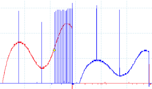
The sensor will test the adc value after 1.8ms, 3.6ms and every 100us since 4.5ms. Then the output is cleared and n is inversed (and all start again). The curve looks like this :
The red curve is the negative adc input, and the blue curve is the positive adc input. We can see that on the red curve, glitches are coming from DIO5 when I do measure with adc. On blue curve, there is no test every 100us because the system detected that curve is false. It seems that the glitches will interfere on the reading and the blue curve will always be detected as incorrect.
I also tried by using asynchronous adc sampling, and i get a 1.2V offset on DIO5 !! The adc reading as, in this configuration, an impact on DIO5, unfortunately used this time for adc readings.
Any help is welcome, I don't know how to suppress this behavior or if I have to change my design ?
Thanks in advance


