This thread has been locked.

If you have a related question, please click the "Ask a related question" button in the top right corner. The newly created question will be automatically linked to this question.

how to debug bluetooth RF signal issue ?

Other Parts Discussed in Thread: CC2541, CC2540

Hi All ,

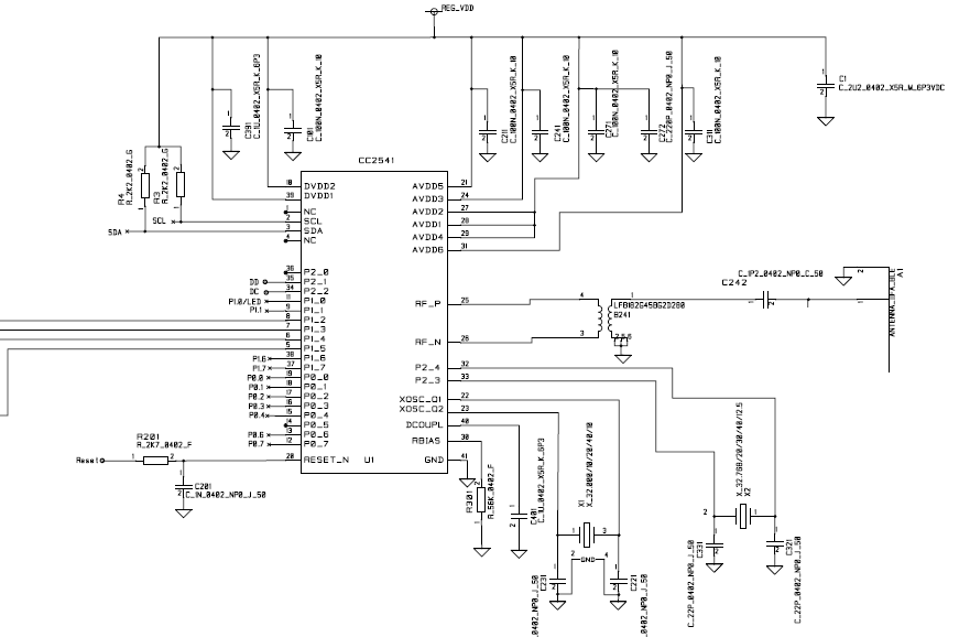
     Has anybody faced bluetooth RF no signal issue ? now I am design a PCB board with bluetooth RF , I use cc2541 and cc2540 the RF circuit I  copy cc2541 sensortag , all the RF component (LFB182G45BG2D280 ) are same as sensortag's .  after I mounted the component , I can program it through smartRF05EM board , when I run my apps , but there is no bluetooth signal from my RF design coming . So I used smartRF Studio 7 to debug it , I also can't find signal . The picture below inside blue line  is my RF PCB layout  . if you find anything wrong or know how to debug it  , Could you please share with me ? thanks in advance ! .


  • Hello,
    Which lines have you connected to your debugger? You need to connect DD, DC, VDD, GND and RESET. You must also make sure to power the board in addition to connecting the debugger. Have you measured the supplied voltage to your device and verified the voltages on the CC2541 power pins (AVDD/DVDD)?

    I could not find any errors in your schematic. For the Layout I have some comments given below. The rule of thumb is to copy the reference design as close as possible! This is very important. Especially anything related to RF and XTAL. But i could not find any direct clue to why your debugger cannot get contact with the CC2541 on your board.

    Layout:
    - Do not use VIAs for the routing to the oscillator crystals (XTAL).
    - You should have more than a single ground via under the ground (center) pad on the CC2541. Try to copy our ref design.
    - Place decouple closer to pin AVDD3
    - Place decouple closer to pin DVDD2
    - Try to get more ground plane. Do you have a ground plane below layer 1?
    - Look at how we implement the ground and matching compoenents between the Balun and antenna in our reference design and try to copy to your best ability.

    Here is a design guide for our new part (CC26xx), but many of the bullets are valid for CC2541 designs as well:
    processors.wiki.ti.com/.../CC26xx_HW_Checklist

  • Dear Eirik ,

    Thanks for your detail infos and suggestion , I will follow your suggestion .
    I have a question about this , when I open device control panel through the smartRF Studio,
    for my design , there is no register view option , so I can't see all the registers related to RF .
    but when I changed my design to TI cc2541 sensorTag , I can see register view option there ,
    So I can see all the register value . Do you know what step I did miss ? any RF registers I can directly control to verify
    whether my no RF signal is because of configure setting or design issue ? thanks !

    BR
    Shijun
  • Simply double click on the CC2541 icon and choose proprietary mode.
  • Hi Eirik , Sorry for misled you . For currently I only want to verify RF , So I am using CC2540 , Does CC2540 don't have register view when verifying RF ? May I know whether I can verify RF function without any design firmware or even wrong firmware ? Thanks!
  • Hello Shijun,
    The CC2540 is a BLE device only and does not support proprietary mode. You should able to verify functionality of the RF by sending packet between two devices using the standard BLE interface in SmartRFStudio. You do not have to flash any image to the device to do this as they are controlled directly through the debug interface. Simply use BLE packets as they wil have the same format on CC2540 and CC2541. (All BLE radios use the same modulation and packet format)

    The 32 MHz oscillator has to run for any allow any RF operation. Have you mounted the load capacitors on your 32 MHz XTAL? Do you have a spectrum analyzer? If so you can set up a continuous wave (TX) to verify if your design can transmit any signal at all.
  • Thanks Eirik! I already mounted 32M XTAL with two capacitors . But I don't have spectrum analyzer , I can't measure them . But before that I did use flash programmer to program this design and flash programmer verify it ok , due to that , Can I say 32M XTAL already work proper ? Am I right ? One more thing , if I did layout not perfect , at least I can see some signal change from another receiver waveform inside smartRF studio when I start transmit data , is it true ? Thanks!
  • You can download code without the 32 MHz oscillator (the device will then run on the internal 15 MHz RCOSC). Even tough you can download code through the debug interface this does not mean that the 32 MHz OSC is running and if it is not running you cannot do any TX or RX operation on your board.

    You can use the online software examples to verify if your 32 MHz Crystals starts up by using the clock examples in CC2541/43/44/45 Peripherals Software Examples .
  • Hi Shijun,

    It looks like you have connected DCOUPL to ground.

    Cheers,
    Fredrik
  • Hi Fredrik ,

    Thanks , actually I connected DCOUPL to a capacitor . Is that correct ? Thanks !

    BR
    Shijun
  • It should be connected to a 1 uF capacitor. In the layout you posted above it looks like pins 39 (VDD) and 40 (dcoupl) are connected.
  • Hi Fredrik , thank you so much ! It's my mistake . I connected DCOUPL to a capacitor and I place VDDI net name over there . Thanks for pointing my mistake . BTW , Do you have cc2541 sensorTag PCB file which can be opened by PROTEL ? Thanks !

    BR
    Shijun