This thread has been locked.

If you have a related question, please click the "Ask a related question" button in the top right corner. The newly created question will be automatically linked to this question.

CC2640 as SPI slave. NPI / TL protocol

Other Parts Discussed in Thread: CC2640

Hi everybody,

We are developing a product where CC2640 is conected by SPI to a main MCU (MKL27 from Freescale). We have implemented NPI over SPI (as described, for example here: processors.wiki.ti.com/.../Cc2640_Adding_a_UART_or_SPI_driver_to_a_Sample_Project) to solve communication between them. SPI/NPI communication is bidirectional: both chips can read and write on bus at any given time (if it is not busy, of course).

We are having some strange problems: communication starts working, but it fails after some minutes (https://e2e.ti.com/support/embedded/tirtos/f/355/p/458078/1654073#1654073). Revising and analyzing TL protocol, we have found some issues we don't understand.

To expose the first one, consider the case when slave (CC2640) writes. The timing diagram documented in in http://processors.wiki.ti.com/index.php/Cc2640_Adding_a_UART_or_SPI_driver_to_a_Sample_Project#TL_Protocol shows that "The data transfer is ended by the master raising MRDY followed by the slave raising SRDY. "

Analyzing the code, we see that raising MRDY and SRDY are independent events triggered by the corresponding callbacks in the corresponding SPI driver implementation of each driver (that is, the driver in the master MCU raises MRDY when it detects transaction finished, and the driver in the slave (CC2640) raises SRDY when it detects transaction is finished).

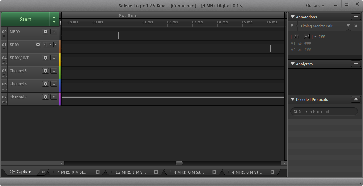
Moreover, if MRDY raising was detected in the slave side before the transaction is marked as finished in its side (that is also the event that raises SRDY), then the function SPICC26XXDMA_transferCancel() would be called to cancel transaction. So we don't understand that order (MRDY raising before SRDY raising) in that diagram. Also, we have made some captures using a logic analyzer, and we see that MRDY is lowed and raised a few microseconds after the corresponding SRDY edges:

In any case, as said, the raising edges are completely independent in our code. In fact, using a breakpoint we have observed that after some minutes raising MRDY must be happened first, because SPICC26XXDMA_transferCancel() is called to cancel a current NOT NULL transaction.

Could you explain me this issue of the diagram? Should we do something to synchronize in any way the raising edges of MRDY/SRDY? In that case, which of them should be trigered first?.

Thank you very much.

Regards.

José Antonio Martínez.

  • Hi Sontono,

    Which SDK product are you working with? I'm not sure this is a TI-RTOS question.

    Once I know more details about what software product(s) you are using, I can get your question to the right folks.

    Steve
  • Hi Steven,

    These are our environment's details:

    CC2640: Chip revision 2.2. Package size: 5x5 (RHB QFN32)
    BLE SDK: ble_cc26xx_2_00_00_42893
    XDCtools: 3.30.6.67_core
    TI-RTOS for SimpleLink Wireless MCUs: 2.11.1.09
    BIOS: bios_6_41_02_41
    UIA: uia_2_00_02_39
    Compiler: TI v5.2.0 [TI v5.2.5]
    CCS: 6.1.0.00104
    SmartRF Flash Programmer 2: 1.6.1

    Thank you.
    Regards.
    José Antonio Martínez.
  • Hi Sontono,
    The NPI protocol is specific for the Bluetooth LE stack so I am moving the thread to correct forum.

    Regards,
    Svend
  • OK. Sorry.
    Thanks Svend
  • Hi Jose,

    I understand that MRDY/SRDY wording is confusing in our wiki. I will work to update it. This is from our SNP software developer's guide:

    "The timing diagram in Figure 8 shows that MRDY is de-asserted only after the transfer on the serial

    bus has completed. This behavior however, is dependent on which underlying serial bus is being used.

    For SPI, the SNP has no concept of when the SPI transfer has finished because the AP is in control of

    SCLK and determines how many bytes are clocked. It is the AP’s job then to clock the correct amount

    of bytes and then de-assert MRDY which signals to the SNP that the transfer has indeed completed.

    The correct amount of bytes is determined by a length field that is present with the SPI frame that is

    being transferred."

    Though you may not be using the SNP, this blurb applies to the NPI protocol with SPI. Does that clear things up? Regarding your issue from the other E2E thread, I will look into the issue more and comment in that thread.

  • Hi Sean,

    Thank you for your interest.

    After reading your explanation (and more details in the SNP software developer's guide), I still have the same doubt.  I will try to summarize it in the following points , all of them related to the provided NPI implementation (please, feel free to comment, clarify or correct the ones you consider):

    1. SRDY de-assertion is governed only and exclusively by the own slave's SPI driver (NPITL_transmissionCallBack()).
    2. MRDY de-assertion must be governed only by the master SPI driver (implementation not provided).
    3. So, there is NOT a direct relationship (cause-effect or temporary) between the two de-assertions, and there is nothing that guarantees which de-assertion is detected first in the slave side (my tests also seem to confirm this behaviour: for transactions started by the slave, most of times SRDY de-assertion happens first, but sporadically MRDY is detected first).
    4. If MRDY is detected first, then SPI transaction is cancelled.

    Are these points true?

    Thank you very much.

    BR

    José Antonio Martínez.

  • Hi,

    I added a post in the other thread e2e.ti.com/.../1667189 related with this issue.

    Thanks
  • Hi Jose,

    I apologize for the delay. I have looped in our NPI developer and we are working on this today. I will have answer to your above questions shortly. Also please disregard my last response since I was mistaken and thought you were using a simpleNP implementation.
  • Jose,

    I have commented in your other post. Please take a look and get back to me.
  • Jose,

    I am commenting your last post from the RTOS forum here for context:

    Hi Sean,
    Some points I would like to clarify:
    1. Do you mean a capture of any transaction or a capture in the moment that the problem appears? If it is the second, I guess it is almost impossible: there are several thousands of correct transactions until the problem appears, and with my logic analyzer I am only capturing one transaction each time (triggering capture with lowing edge of SRDY for example). Maybe can I capture more transactions each time? any suggestion?.
    2. To see all the remaining SPI signals I will need to request our HW team to develop a product exposing that trails, since our custom board has not pins to that signals. I can not promise you if we will have advances achieving this point.
    3. You say "MRDY should always have a rising edge before SRDY" but this confuse me a lot, since this is not what I see in my captures, and also it is not what I should expect that the code is working. Moreover, in this case, I don't understand the explanation: "The NPI master must parse the message coming from the slave to know when to assert MRDY".

  • Now that we have established this thread as the one to move our discussion forward on, let me answer your questions.

    1. yes if need be just capture a bunch of transaction. I believe the Salae model is really only limited by how much space you have on your PC. In order for the traces to be reduced in size you can reduce your sampling rate. Always be sure that you're at least ~5x as fast as the SPI clock to get an accurate picture of whats going on.

    2. I understand this may be difficult because of your hardware setup, but it is very very important to root-causing this problem. You could possibly scrape the silkscreen and green wire to these traces until your HW team builds a platform with some testpoints

    3. Correct. Regardless of what transaction type NPI defines that MRDY will always be raised first (before SRDY). I understand that you are not seeing this in your captures, and I believe this could be due to your NPI implementation on your master device (the MKL27). What I mean by the responsibility being on the master to parse the packet is that the NPI SPI format has a length field (SPI packet diagram here: processors.wiki.ti.com/.../File:Spi_format.png). The NPI master must use this length field to keep track of how many bytes they have rx'd and use that to raise MRDY.

    Does this make sense?
  • Hi José,

    Did you also test anything more wrt using only 1 SPI instead of 2?

    I have found a -potential- (still not verified) issue wrt power management in the SPI driver if a transaction in one SPI module finishes while the other one is still ongoing and nothing else in the application has set a constraint on standby. Haven't looked very much into the details yet but it seems iy could cause the chip to go into standby while there is still an ongoing transaction on the other SPI.

    From the looks of your exception I don't think this is affecting you but we would know more if this would be the case if you are able to capture the SPI data while the issue occurs.

    Regards,
    Svend
  • Hi Svend,
    In fact, I was working some hours in that way, and I could not reproduce the issue using only one SPI. However, it is a little complicated to extract a clear conclusion from that test, since one of the main sources of data transmitted by NPI are precisely the inertial sensors connected in the other SPI, so, when using only the SPI channel used for NPI I am also changing the data (rate and frequency transmitted). Of course, I was generating data trying to simulate the accelerometer as a source, but I can not guarantee that I am reproducing exactly the conditions that make the NPI fail.

    I will keep trying to capture SPI data to share with you.
    Thank you very much.
    BR
    José Antonio Martínez.
  • Hi Sean, Svend,

    At the end, I have captured a bunch of transaction with all SPI signals:

    20151111_1726_fail_at_95M_4_MHz_240_M_Samples.zip

    I have a breakpoint in the SPICC26XXDMA_hwiFxn() function, just when the fail is detected (as a null pointer object->currentTransaction). This breakpoint stops execution aprox. at 21sg. from the start of the capture (as you can see, after this point only MRDY line has activity).

    Could you please take a look to this capture to see if it can help understand what is happening. Of course, I am fully available to any test or explanation about the capture that you need.

    Thank you very much.

    BR

    José Antonio Martínez.

  • Hi again,

    All this time, I'm still trying to determine if the problem can be reproduced using only one SPI channel. Only for this purpose, I disable all code that uses SPI0 and generate some data to send over SPI1 (simulating the data generated by accelerometer connected in SPI0). Doing this, I note that CC2640 stops sending data over NPI/SPI0 after some seconds (about 55 seg. in this test). Capturing data with analyzer, I see a weird behaviour (from my point of view) in the MISO line: it stays low "too much" time:

    20151112_1029_miso_stays_low_4_MHz_240_M_Samples.zip

    I already noted this behaviour when running in "normal mode" (both SPI channels working), as it can be seen in the previous capture. However, it this case I noted that MISO even remains low between two consecutive transfers (at 53sec. and 56sec. aprox.). I don't know if this is related with the original problem or with the fact that the CC2640 stops sending data over NPI aprox. at this same time.

    Thank you very much.

    BR

    José Antonio Martínez.

  • Hi,

    Last researches lead me to the following point: my NPI code is exactly the original one provided with ble stack 2.0.0, except for two things:

    a) Define SRDY and MRDY pins for our design in npi_config.h

    b) We had to comment the following line in NPITL_transmissionCallBack() function:

    #ifdef POWER_SAVING
    // Reset mrdy state in case of missed HWI
    //mrdy_state = PIN_getInputValue(MRDY_PIN);

    Now, it seems that this can be related, at least, with the behaviour of the MISO line. I take a look to code managing this variable (mrdy_state) in the new ble stack version (2.1.0) and I see that the following lines were added at the end of NPITL_MRDYPinHwiFxn():

    // Check the physical state of the pin to see if it matches the variable
    // state. If not then edge has been missed
    if (mrdy_state != PIN_getInputValue(MRDY_PIN))
    {
    mrdy_state = PIN_getInputValue(MRDY_PIN);

    if (mrdy_state == 0)
    {
    mrdyPktStamp = txPktCount;
    NPITL_setPM();

    if (taskMrdyCB)
    {
    taskMrdyCB();
    }
    }
    else
    {
    transportStopTransfer();
    }
    }

    So, I uncomment my change in NPITL_transmissionCallBack() and added this lines to manage mrdy_state in the same way as the ble stack 2.1.0 is doing it, and what I see is that MISO is now in low state most of time (instead of high state as I would expect):

    20151112_2251_fail_with_new_version_npi_code_4_MHz_240_M_Samples.zip

    I am not still able to explain this behaviour from the changes in the code, but what do you think? maybe is all this issue with the "mrdy_state" var and the MISO line behaviour related with my fail?. If I don't find another way I will try to update ble stack, or at least the full NPI component (could it be updated separately?) to see if it solves or changes anything.

    Any suggestion is welcome. 

    Thank you very much. BR

    José Antonio Martínez

  • Hi,

    I have replaced the full npi component (taking folder Components/npi from ble_2_1_0). It is fully compatible with the version of ble_2_0_0, I only had to do two modifications:

    1. Define my own MRDY/SRDY pins in npi_config.h (we are using IOID_9 and IOID_13).
    2. Change calls from NPIRxBuf_GetRxBufLen() to NPIRxBuf_GetRxBufCount() in my app.

    Everything else is the original NPI code from 2_1_1.

    Tests have reproduced the same failure (breakpoint triggered when unexpected object->currentTransaction == NULL in SPICC26XXDMA_hwiFxn()), though it seems that is "more dificult" to reproduce it (I needed about 10 minutes transmitting data, when tipically it failed in about 1/2 mins with the 2_0_0 original code).

    By the way, this is the new capture of this test (fail detected and breakpoint triggered about 40 sec.):

    20151113_1123_full_npi_2_1_0_ported_4_MHz_240_M_Samples.zip

    Any ideas or comments?

    Thank you very much. BR

    José Antonio Martínez

  • Hi again,
    From another point of view, we also have a memory flash (spansion s25fs-s) connected to the Freescale MKL27. So, we disabled all NPI communications between the MKL27 and the CC2640 and study communication with the flash. What we see is a "normal" MISO behaviour: it stays high all time, except the moments needed for transmit data (but recover high state inmediatelly), so it seems that the behaviour of CC2640 as SPI slave in my NPI configuration is not fully correct. Do you think so?

    Thank you. Regards.
    José Antonio Martínez.
  • Hi again,

    I have been reading about MISO and required pullup/pulldown on this SPI line. After that, I am thinking that maybe the MISO behaviour is not the related with the problem detected. It seems (as explained for example here ) :

    "As far as I know, SPI lines are always actively driven in both directions.

    I sometimes put a pulldown on the MISO line because it could be floating for extended periods of time. Only the slave with slave select asserted is allowed to drive the line, so when no slave is selected, the line floats.

    Floating MISO doesn't cause any data problems because it only floats when its value is meaningless and the master shouldn't be looking at the line anyway. However, intermediate voltages on some digital inputs can cause trouble. They can cause oscillations and higher than specified current draw inside the receiving chip. A weak, even 100 kΩ, pulldown keeps the line at the logic low level when not in use."

    What do you think? Do you agree? Any suggestions or ideas?

    Thank you very much. Regards.

    José Antonio Martínez


  • Hi José,

    I have notified Sean again on this thread.
    The MISO pin on the CC26XX SPI is high impedance when not used (CSN is high) but there is a pull-down enabled on that pin in the driver to avoid undefined voltage levels and high current draw on the corresponding pin on the host processor.

    Edit: This applies only to SPI master mode. For slave configuration the following is set in the driver:

          spiPinTable[i++] = hwAttrs->mosiPin | PIN_INPUT_EN;
          spiPinTable[i++] = hwAttrs->misoPin | PIN_GPIO_OUTPUT_EN | PIN_GPIO_LOW | PIN_PUSHPULL | PIN_INPUT_DIS | PIN_DRVSTR_MED;
          spiPinTable[i++] = hwAttrs->clkPin  | PIN_INPUT_EN;
          spiPinTable[i++] = object->csnPin   | PIN_INPUT_EN | PIN_PULLUP;

    Regards,
    Svend

  • Hi José,

    Apologies for taking so long to respond. I will look through all the information you have updated us with and get back to you by end of the day today.
  • Hi José,

    I'm looking into the issue now. Since you have provided a lot of data as you were working on the issue. I will start from the most recent (where you ported to NPI from BLE Stackv2.1). When you updated NPI are you still using the old RTOS or are you using 2.13.06?
  • Hi Sean,

    In my tests, I am always using TI-RTOS 2.11.1.09. (the one provided with the original ble sdk we are using 2.0.0). Specifically, all components are the ones reported in e2e.ti.com/.../1687802 (as commented in previous posts (https://e2e.ti.com/support/embedded/tirtos/f/355/p/458078/1656045#1656045) we are trying to port and update all our project to the new versions, but this can not be done yet).

    Thank you. BR.
    José Antonio Martínez.

  • Thank you José.

    Looking at the SPI drivers from the 2.11 RTOS. It seems to me that there are a few ways the currentTransaction can be set to NULL:
    1. Opening the SPI driver
    2. Later in the HWI function that you're breaking in
    3. Calling transfer cancel
    4. Memory corruption (doubtful, lets discount for now)

    Also, I cannot yet pinpoint this to being your issue, but it seems like the last transfer which occurred before you broke did not follow the NPI packet format:
    at ~39s:284ms you send a SOF on MOSI. This is the first byte of the current transaction. According to the NPI frame format for SPI, the following byte should be the length byte, which can be between 0-255. You set the length byte to 0x1C (28 in dec), but then send many more bytes. There should be one spi frame (SOF, LEN, payload, FCS) per handshake. This is vital to the NPI protocol working correctly.

  • Furthermore, I haven't taken the time to count them (Salae doesn't offer an easy way to do this), but it looks like you may be sending more than the max allocated NPI buffer per transaction which 270 bytes as mentioned earlier in this thread. In this case, you will call transfer cancel through NPI which will cause your fault.

    To fix your issue:
    make sure that you are only sending one SPI frame per handshake. You must adhere to the frame format described on the wiki you linked to in order for NPI to be useful. That is, after you have transmitted LENGTH number of bytes, the transaction should cancel and you should raise MRDY. If there is still data you need to send, then you will need to start the transaction process all over again.
  • Hi Sean,

    Thank you for your answers. Some points I would like to clarify:

    1. My NPI packet is tipically 28 bytes length. However, the original NPI implementation you provided always transmit "NPI_TL_BUF_SIZE" bytes (fixed to 270). Regarding to the last transfer you refer, there is a SOF(254), then LEN(28), and then  payload (28 bytes) and FCS (which is 20 for that packet). The rest of the bytes (until 270) are 0, but they are added by the own NPI implementation. That is, at the end I am calling the function NPITLSPI_writeTransport(len) to transmit, with the param "len=28", that is the length of my packet, but since NPI_TL_BUF_SIZE=270 this function completes until 270 bytes (with zeros as I can see) when transmitting using SPI_DRV_MasterTransfer(). Is that correct? or is there any adjust I should be doing?.
    2. Regarding the points that can cause currentTransaction to be NULL, they are the same ones as I had detected. From my investigations I think the most probable cause in this case is 3, since I was debugging and I could discard 1. and 2. when reproducing the issue. I could not discard 3 yet, and I still don't understand the reason that could cause such behaviour (maybe a sort of race condition...?)...

    Thank you very much.

  • Sean,
    I think there is a sort of misunderstanding here. As commented in my previous post, my NPI packet is always 28 bytes length (or less in some rare cases). The captures show that each transaction is transmitting exactly 270 bytes (this is true in all cases I have counted, and I have exported search results to Excel to analyze data), but as commented previously, this is a consequence of the NPI implementation that I do not touch. Specifically the function NPITLSPI_writeTransport() will transmit always NPI_TL_BUF_SIZE bytes regardles of the len that it receives as parameter (that is the length of my packet). I never have to transmit more than NPI_TL_BUF_SIZE bytes, since my NPI packet len is much lower. So, what am I doing wrong?

    Thank you very much. BR
    José Antonio Martínez.
  • José,

    I agree that there is likely a misunderstanding. What I am saying is that I recognize that your desired payload is only ~20B, but the issue is that you are in fact sending 270B. Sending a payload larager than 270B will cause SPI_transferCancel to be called which will null out your current transaction object, thus causing the crash you're seeing. This is not a bug in NPI, this is in fact how it is designed. I have spoken with the author of the code and confirmed this.

    The developer states that ideally a frame with LEN=20B will consist of this:
    (in order of appearance on SPI lines)
    MRDY/SRDY handshake|SOF| LEN | PAYLOAD | FCS | MRDY/SRDY handshake

    Stated differently, that means, if LEN = 20B then only 20B (plus FCS, SOF, and LEN) will be transmitted in the frame. The fact that you are seeing the 250 extra zero bytes means there is an error somewhere.
  • Hi Sean,

    OK. I understand, but then, since I am using the original (untouched) NPI code, that is, I am using the function NPITL_writeTL(uint8 *buf, uint16 len), where len=28, then, any idea about where could be the error?. It seems that there is not much to do in my app code before calling the NPI write fuction, right?

    Thank you very much. BR
    José Antonio Martínez.
  • Hi José,

    It is hard to tell exactly without seeing your code. Since your setup is unique I have not yet tried to recreate it. This still may be an error that stems from multiple SPI devices running at once. Quick question: you're only using one of these SPI devices with NPI correct? NPI is only written for one device target if I am not mistaken.

    here is I would recommend to try:
    1. Use the TL protocol from processors.wiki.ti.com/.../Cc2640_Adding_a_UART_or_SPI_driver_to_a_Sample_Project
    to read and write data from your app over SPI.
    2.Disable all other writes and reads at this time. Lets focus on this one first
    3. There are logic captures posted on the wiki, try to see if you can't get your frames to look similar
    4. From there we can expand and see where things break.
  • Hi Sean,
    I am going to proceed with your recommendations right now. Before starting, just some clarifications:

    1. Indeed, I am using NPI/TL only to communicate [CC2640(SPI1) (slave) <-> MKL27 (master)]. On the other way, CC2640 uses SPI0 to communicate with accel/gyro (no NPI used here), and MKL27 uses the same SPI channel as used in NPI to communicate with the flash memory (no SPI used here either, moreover this communication is disabled by now).

    2. I am already using TL protocol over NPI. I was referring to NPITL_writeTL() function for simplicity, but over all I am using the TL layer.

    3. As said before, I can not reproduce the issue if I disable all other writes and reads (the ones in SPI1), but this changes the environment test conditions in many ways, since most of the data transmitted over NPI comes from the acc/gyro in SPI1 (and yes, I am simulating this data generation, but the rates etc. maybe are not the same).

    Once clarified these points, I am going to analyze logic captures in the situation you suggest (only NPI/TL communication active in SPI). I will keep you updated with my results.

    Thank you. BR
    José Antonio Martínez.
  • Hi José,

    Thanks for the info. I think this will be insightful to figuring out whether this issue exists at the SPI driver level or the NPI level or if they are tied together.
  • Hi Sean,
    I have configured a test environment with the following conditions:

    • CC2640 only uses SPI1, where it is configured as a SPI slave, to try to transmit a TL/NPI packet each second. No SPI0 is used nor initialized.
    • MKL27 does not transmit. It is configured as a SPI master, and only reads transmissions from CC2640.

    Then, I observe the following:

    Each time CC2640 wants to transmit a packet it does the following:

    1, It configures SPI_transfer() to transmit 270 bytes (NPITLSPI_writeTransport()):

    // set up the SPI Transaction
    spiTransaction.count = NPI_TL_BUF_SIZE;
    spiTransaction.txBuf = TransportTxBuf;
    spiTransaction.rxBuf = TransportRxBuf;

    // Check to see if transport is successful. If not, reset TxBufLen to allow
    // another write to be processed
    if( ! SPI_transfer(spiHandle, &spiTransaction) )

    2. Enables SRDY: (NPITL_writeTL()):

    SRDY_ENABLE();

    Then, it's the SPI master code on MKL27. Originally, it was configured to read NPI_TL_BUF_SIZE (270) bytes, so, as the master, it generated clock until this amount of bytes were readed, then it raised MRDY to finish transaction. This situation corresponds to the captures already discussed in previous posts, where there is a padding of zero bytes until reaching 270 bytes. From your comments, and the documentation it seems to me that master should use the known TL packet length to raise MRDY when the suitable number of bytes have been received, without expecting to complet 270 bytes, am I right?

    What I have found is that if I change master implementation to read a lower number of bytes (for example 170), then what happens is next:

    1. After MRDY deassertion, clock is generated by master until these 170 bytes are received. As in previous case, zero bytes are readed from the end of the NPI/TL packet until 270 are reached, so I guess this is right, is that true?
    2. NPITLSPI_CallBack() is never called, so SRDY is never deasserted and no more that one transmission can be done. Is this behaviour expected? In that case, I guess that I can not configure master to read only the amount of bytes that corresponds to the NPI/TL packet. It had to read always the same NPI_TL_BUF_SIZE (270) bytes before deasserting MRDY (which is not what I understand from you comments as said before).

    This behaviour can be seen in the following analyzer capture:

    20151119_2022_size_master_150_4 MHz_80_M_Samples.zip

    Could you help me clarify all this mess?. Thanks a lot.

    José Antonio Martínez

  • Hi José,

    Please revert back to the case where NPI_TL_BUF_SIZE = 270. You should also leave the NPITLSPI_writeTransport() function untouched.

    The basic idea is this, as I have said earlier in the thread:

    1. 1. NPI kicks off a (270 by default, but really this is just chosen to be arbitrarily large) byte read for every transaction on the slave side. This transaction is started with the intention that it will not finish.
    2. 2. Instead of sending out 270 bytes of 0x00 (useless data), the NPI SPI slave expects that the master will
      1. Read the "header" i.e. SOF and LEN fields. The header is always 2 bytes. This means from master POV each frame starts with 2B read.
      2. Based on the header LEN field, it will kick off a read of N bytes, where N is the data within the LEN field (0-255).
      3. Once the payload (LEN = N) has been read, the master will raise the MRDY line.

    Rising MRDY event stops the current transfer on the slave side long before 270 bytes are ever transferred. Please implement this code on your master side and see if you cannot replicate the a similar logic trace to that which is on the wiki.

  • Hi José,

    Sure, I'm here to help. NPI can be confusing, I understand that. I just suggested this post as an answer so other forum goers could see the "proposed" resolution of the first issue we were seeing (object->currentTransaction == NULL crashes).


    It looks like your response is not showing up here for some reason, but I saw it in my email and reviewed the trace. We are getting close!
    Within the NPI slave (26xx in your case) SRDY is pulled high within NPITL_transmissionCallBack (in NPI_tl.c) , which should be triggered after your frame is sent. Can you put a breakpoint in this function and see if you are reaching it?

  • Hi Sean,
    Thank you for your help, and sorry for unmark suggested answer. What I was trying to do was to reply to your answer adding more info, but, in fact, I deleted my answer some minutes after have writted it. Please discard the info it contains. I was forgotten a minimal hack added by myself to original NPI code during test: that is, as said some days ago, I had commented the call to transportStopTransfer(). Then I forgot to undo this change, and this was causing the SRDY/MISO lines not to be rised. I recover full original NPI code (and check it fully this time!), and now SPI transactions have exactly the expected form in the logic analyzer captures.

    I still can not say if the null pointer issue still remains with the changes in the NPI master implementation (now there is not zero padding until 270 bytes). Please, let me make some tests this weekend and I will inform you about the results at the beginning of the next week.

    Sorry for the annoyance caused, and thank you very much. BR

    José Antonio Martínez.

  • No worries! Post the results here, and then if good, we can move forward with bringing the second SPI into this. I believe your issues should likely be resolved but it will be good to know that you can use both SPI ports on the device and not have them conflict with NPI.
  • Hi Sean,

    Indeed, as you well anticipated, the problem seems to be fixed. I have been testing the product these days with full functionallity (both SPI channels working in CC2640), and I could not reproduce any fault. So, to summaryze, at the end, the cause of the problem was a faulty NPI master implementation. Implementing the algorithm you suggested (read NPI/TL packet's header first and then read the remaining packet's bytes) not only seems to fix my problem, also it let me optimize the memory used in transmission buffers.

    So, I would like to express my gratitude for all your help with this issue. 

    Best wishes.

    José Antonio Martínez.

  • Hi José,

    Great to hear that you solved your problem. NPI can be a bit difficult to work with at times but it is a robust protocol when you have multiple CPU's talking to each other.
    If you see anything that could be improved from TI's side here to make error handling more robust, please let us know!

    Regards,
    Svend
  • Hi José,

    I would like to echo what Svend said. We're glad to help you get it working. As always, we will try to incorporate feedback from this thread to make our documentation clearer in the future. Best of luck with your future development.