This thread has been locked.

If you have a related question, please click the "Ask a related question" button in the top right corner. The newly created question will be automatically linked to this question.

gsm module with CC2640 UART problem

Other Parts Discussed in Thread: CC2640, SYSBIOS, CC2650

Hello,

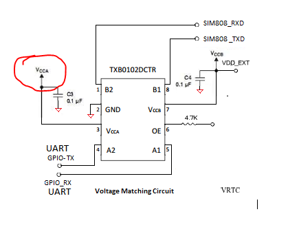
I am interfacing SIM5320J gsm module with CC2640 over UART communication. But i did not receive OK response from gsm module. When i am debugging my code and measure voltage level at gsm Power_ON pin i am getting 2.60V. But I am not getting any response from gsm module. Connection of uart TXD and RXD pins are cross connected with gsm txd and rxd .  Any one worked on this module please suggest me where i am wrong.

code :

#include "Board.h"
#include <ti/sysbios/knl/Task.h>
#include <ti/sysbios/BIOS.h>
#include <ti/drivers/PIN.h>
#include <ti/drivers/PIN/PINCC26XX.h>
#include <ti/sysbios/knl/Semaphore.h>
#include <ti/drivers/UART.h>
#include <xdc/runtime/System.h>
#include "delay.h"

#include "string.h"

static PIN_Handle pinHandle;
static PIN_State ModbusState;

#define TASK_STACK_SIZE 512
#define TASK_PRI 1

char taskStack[TASK_STACK_SIZE];
Task_Struct taskStruct;

void taskFxn(UArg a0, UArg a1);


#define BUFTYPE char
#define PBUFTYPE char*
#define BUFSIZE 15

UART_Handle hUART;

BUFTYPE txBuf[] = "AT\r";
BUFTYPE rxBuf[2];

UART_Params params;

Semaphore_Struct sem;
Semaphore_Handle hSem;

static void uartRxCb(UART_Handle handle, void *buf, size_t count) {
Semaphore_post(hSem);
}

void taskFxn(UArg a0, UArg a1) {
pinHandle = PIN_open(&ModbusState, BoardGpioInitTable);
PIN_setOutputValue(pinHandle, PIN_ID(Board_EN_VBUS), Board_EN_VBUS_OFF);  
delay_ms(100);

PIN_setOutputValue(pinHandle, PIN_ID(Board_MODEM_PWR_EN), Board_MODEM_PWR_EN_ON);   //  modem power supply
delay_ms(1000);
// PIN_close(ModbusHandle);

if(Board_MODEM_PWR_PGOOD) {
PIN_setOutputValue(pinHandle, PIN_ID(Board_MODEM_CONTROL), 0);
delay_ms(50);
PIN_setOutputValue(pinHandle, PIN_ID(Board_MODEM_CONTROL), 1);
delay_ms(120);
PIN_setOutputValue(pinHandle, PIN_ID(Board_MODEM_CONTROL), 0);     // Enable GSM power on
delay_ms(4000); 
}
else {
System_printf("Power not Good\n");
PIN_setOutputValue(pinHandle, PIN_ID(Board_MODEM_PWR_EN), Board_MODEM_PWR_EN_ON);
delay_ms(100); 


UART_Params_init(&params);
params.readMode = UART_MODE_CALLBACK;
params.writeMode = UART_MODE_BLOCKING;
params.readCallback = uartRxCb;
params.readEcho = UART_ECHO_OFF;
params.dataLength = UART_LEN_8;
params.stopBits = UART_STOP_ONE;
params.baudRate = 115200;

hUART = UART_open(CC2650_UART0, &params);

Semaphore_Params sParams;
Semaphore_Params_init(&sParams);
sParams.mode = Semaphore_Mode_BINARY;

Semaphore_construct(&sem, 0, &sParams);
hSem = Semaphore_handle(&sem);

PIN_close(pinHandle);

UART_write(hUART, txBuf, sizeof(txBuf));
delay_ms(1000); 
UART_read(hUART, &rxBuf, sizeof(rxBuf));
Semaphore_pend(hSem, BIOS_WAIT_FOREVER);

if((strstr(rxBuf,"OK")) || (strstr(rxBuf,"ok"))) {
System_printf("AT : OK"); 
}
else {
System_printf("Error...");

}

int main(void) {

PIN_init(BoardGpioInitTable);

Task_Params params;
Task_Params_init(&params);
params.priority = TASK_PRI;
params.stackSize = TASK_STACK_SIZE;
params.stack = taskStack;

Task_construct(&taskStruct, taskFxn, &params, NULL);

BIOS_start();
}

Regards,

Rajneesh

  • Rajneesh,

    Have you looked at the pins with a logic analyzer? I suspect that UART_open returns NULL since you already have opened one of the UART pins (TX) with your PIN_open call.

    Regards,
    Svend
  • Hello Svend,

    yes, UART handle returns NULL. Can you tell me how can i open UART_TX pin separately? So i can perform uart tx and rx operation.

    Regards,

    Rajneesh

  • Hi Rajneesh i am working on cc2650 uart communication with gsm module (SIM808) could u pls help me in coding part

    Thank You
  • Hi Svendbt

    i am working on cc2650 uart communication with gsm module (SIM808) could u pls help me in coding part
  • Hi Rajneesh

    Can you share the the complete code with, even i am working on cc2650 uart connection with sim808, i tried copying your code but getting lots of errors there are many undefined variables are there can u please send me the working code. or if possible send me the defined variables

    Thank You,
  • You can refer to section 6.3.2 UART in SWRU393_CC2640_BLE_Software_Developer's_Guide.pdf.
  • Hi Martin,

    I have not worked on sim808. Above code is according to my custom board configuration and just checking code weather gsm modem working or not by sending(AT\r) command. But you have to first read AT commands for sim808 modem and transmit AT commands through UART_write and get response from gsm modem by calling UART_read.

    Remember - set correct baud-rate other wise uart read garbage value or null and please verify uart RXD and TXD pins are cross connected with gsm?

    Best wish
    Rajneesh

  • Thank You for your valuable replay Mr. Rajneesh 

    I have went through all the AT commands of sim808 series ant i have even worked on terminal all of them r working properly and i tried modifying your code but its printing Error.., i have set the baud-rate of 115200 which s standard from both the controller side and SIM808 side ma modified code as fallowed 

    UART_Params_init(&params);
    params.readMode = UART_MODE_CALLBACK;
    params.writeMode = UART_MODE_BLOCKING;
    params.readCallback = uartRxCb;
    params.readEcho = UART_ECHO_OFF;
    params.dataLength = UART_LEN_8;
    params.stopBits = UART_STOP_ONE;
    params.baudRate = 115200;

    hUART = UART_open(CC2650_UART0, &params);

    Semaphore_Params sParams;
    Semaphore_Params_init(&sParams);
    sParams.mode = Semaphore_Mode_BINARY;

    Semaphore_construct(&semm, 0, &sParams);
    hSem = Semaphore_handle(&semm);

    UART_write(hUART, txBuf, sizeof(txBuf));
    delay_ms(1000);
    UART_read(hUART, &rxBuf, sizeof(rxBuf));
    delay_ms(1000);
    // Semaphore_pend(hSem, BIOS_WAIT_FOREVER);


    if((strstr(rxBuf,"OK")) || (strstr(rxBuf,"ok")))
    {
    System_printf("AT : OK");
    // DEFAULT_SVC_DISCOVERY_DELAY;
    LCD_WRITE_STRING("AT : OK", LCD_PAGE2);
    }
    else
    {
    System_printf("Error...");
    // DEFAULT_SVC_DISCOVERY_DELAY;
    LCD_WRITE_STRING("Error...", LCD_PAGE3);
    }

    this is the code and i have not used 

    int main(void) {

    PIN_init(BoardGpioInitTable);

    Task_Params params;
    Task_Params_init(&params);
    params.priority = TASK_PRI;
    params.stackSize = TASK_STACK_SIZE;
    params.stack = taskStack;

    Task_construct(&taskStruct, taskFxn, &params, NULL);

    BIOS_start();
    }

    this loop and the power management loop that u have used is it bec of that am not getting the correct response. 

    Thank You,

  • Hi,

    Put break point on this line, if((strstr(rxBuf,"OK")) || (strstr(rxBuf,"ok"));

    and check rxBuf containts in view > watch1 or you can print by System_printf(rxBuf);

    Let me tell what you receive in rxBuf.

    And try to set your baudrate 9600.

    Regards,

    Rajneesh

  • Hi Rajaneesh 

    I tried with both the baud rate(9600/115200) and in rxBuf the value i received is this 

    (x)=[0]                        0(Decimal)                                0x2000209A(Address)
    (x)=[1]                        0(Decimal)

    void SimpleBLECentral_createTask(void)
    {
    PIN_init(BoardGpioInitTable);
    Task_Params taskParams;

    // Configure task
    Task_Params_init(&taskParams);
    taskParams.stack = sbcTaskStack;
    taskParams.stackSize = SBC_TASK_STACK_SIZE;
    taskParams.priority = SBC_TASK_PRIORITY;

    Task_construct(&sbcTask, SimpleBLECentral_taskFxn, &taskParams, NULL);
    BIOS_start();
    }

    This is the task i have created.

    Board_EN_VBUS_OFF;
    Board_EN_VBUS;
    Board_MODEM_PWR_EN_ON;
    Board_MODEM_PWR_EN;
    ModbusState;
    pinHandle;
    pEvent;
    MODEM_PWR_PGOOD
    MODEM_CONTROL
    EN_VBUS

     */ Can u tell me what u have defined for all these variables. 

    Thank You,

  • Hi Martin,

    Give me your schematic (gsm interface with CC26xx).

    Regards,
    Rajneesh
  • Hi,

    You have to follow below steps:

    1. Enable Vcca pin. 

    2. GPIO-TX and GPIO-RX pin map with IOID in Board.h file (refer CC2640 datasheet).

     For e.x. - In my case

    #define Board_MODEM_TXD       IOID_15
    #define Board_MODEM_RXD       IOID_14

    3. Initialize these pin in Board.c file

     For e.x. - In my case

     Board_MODEM_TXD | PIN_GPIO_OUTPUT_EN | PIN_GPIO_HIGH | PIN_PUSHPULL,
     Board_MODEM_RXD | PIN_INPUT_EN,

    4. Application code

    #include "Board.h"
    #include <ti/sysbios/knl/Task.h>
    #include <ti/sysbios/BIOS.h>
    #include <ti/drivers/PIN.h>
    #include <ti/drivers/PIN/PINCC26XX.h>
    #include <ti/drivers/UART.h>
    #include <xdc/runtime/System.h>
    #include "delay.h"

    #include "string.h"

    static PIN_Handle pinHandle;
    static PIN_State ModbusState;

    #define TASK_STACK_SIZE 512
    #define TASK_PRI 1

    char taskStack[TASK_STACK_SIZE];
    Task_Struct taskStruct;

    void taskFxn(UArg a0, UArg a1);


    #define BUFTYPE char
    #define PBUFTYPE char*
    #define BUFSIZE 15

    UART_Handle hUART;

    BUFTYPE txBuf[] = "AT\r";
    BUFTYPE rxBuf[20];

    UART_Params params;

    Semaphore_Struct sem;
    Semaphore_Handle hSem;

    void taskFxn(UArg a0, UArg a1) {

    UART_Params_init(&params);
    params.readMode = UART_MODE_CALLBACK;
    params.writeMode = UART_MODE_BLOCKING;

    params.readEcho = UART_ECHO_OFF;
    params.dataLength = UART_LEN_8;
    params.stopBits = UART_STOP_ONE;
    params.baudRate = 115200;

    hUART = UART_open(CC2650_UART0, &params);

    UART_write(hUART, txBuf, sizeof(txBuf));
    delay_ms(1000); 
    UART_read(hUART, &rxBuf, sizeof(rxBuf));

    if((strstr(rxBuf,"OK")) || (strstr(rxBuf,"ok"))) {
    System_printf("AT : OK"); 
    }
    else {
    System_printf("Error...");

    }

    int main(void) {

    PIN_init(BoardGpioInitTable);

    Task_Params params;
    Task_Params_init(&params);
    params.priority = TASK_PRI;
    params.stackSize = TASK_STACK_SIZE;
    params.stack = taskStack;

    Task_construct(&taskStruct, taskFxn, &params, NULL);

    BIOS_start();

    return 0;
    }

    5. what is CC2650_UART0 ? in my case:

    { /* CC2650_MODEM */
    .baseAddr = UART0_BASE,
    .intNum = INT_UART0,
    .powerMngrId = PERIPH_UART0,
    .txPin = Board_MODEM_TXD,
    .rxPin = Board_MODEM_RXD,
    .ctsPin = PIN_UNASSIGNED,
    .rtsPin = PIN_UNASSIGNED
    },

    6. After following all steps you have to check gsm modem 49 pin (status pin) If status pin high (Apprx, 3.30 V) means modem supply voltage ok.

    Regards,

    Rajneesh.

  • Hi Rajaneesh 

    How to enable Vcca since its external supply and 

     Board_EN_VBUS_OFF;
     Board_EN_VBUS;
     Board_MODEM_PWR_EN_ON;
     Board_MODEM_PWR_EN;
     ModbusState;
     pinHandle;
     pEvent;
     MODEM_PWR_PGOOD
     EN_VBUS

    What u have defined all these let me know bec i have not used this loop 

    pinHandle = PIN_open(&ModbusState, BoardGpioInitTable);
    PIN_setOutputValue(pinHandle, PIN_ID(Board_EN_VBUS), Board_EN_VBUS_OFF);

    PIN_setOutputValue(pinHandle, PIN_ID(Board_MODEM_PWR_EN), Board_MODEM_PWR_EN_ON); // modem power supply
    if(Board_MODEM_PWR_PGOOD)
    {
    PIN_setOutputValue(pinHandle, PIN_ID(Board_MODEM_CONTROL), 0);

    PIN_setOutputValue(pinHandle, PIN_ID(Board_MODEM_CONTROL), 1);

    PIN_setOutputValue(pinHandle, PIN_ID(Board_MODEM_CONTROL), 0); // Enable GSM power on

    }
    else
    {
    System_printf("Power not Good\n");
    PIN_setOutputValue(pinHandle, PIN_ID(Board_MODEM_PWR_EN), Board_MODEM_PWR_EN_ON);

    because i could not define all those variables i guess bec am not using this loop am not getting data transferred please let me know what u have defined 

    Thank You,

  • hi rajaneesh,

    I have fallowed all your steps mentioned in the previous comment except only one that is Vcca i could not understand how to make it enable and I have initialized modem Tx and RX but i have not connected them to SIM808 in code i have initialized
    6. I have tested 49th pin its giving 3.03v
    5. UART0 is

    const UARTCC26XX_HWAttrs uartCC26XXHWAttrs[CC2650_UARTCOUNT] = {
    { /* CC2650_UART0 */
    .baseAddr = UART0_BASE,
    .intNum = INT_UART0,
    .powerMngrId = PERIPH_UART0,
    .txPin = Board_UART_TX,
    .rxPin = Board_UART_RX,
    .ctsPin = PIN_UNASSIGNED,
    .rtsPin = PIN_UNASSIGNED
    },

    Please do help me in solving this prob

    Thank You,
  • HI,

    Please verify Vcca pin directly connected to Vcc Power supply (+3.3V) then no need to enable this pin.

    Otherwise you have to enable this pin. You can enable pin by using 

    PIN_Handle pinHandle;

    PIN_setOutputValue(pinHandle, PIN_Id(pinId), 1);

    Where, pinId indicate IOID no. in your case Vcca pin

    Best wishes,

    Rajneesh

  • Hi Rajneesh 

    I have connected that Vcca to the VDD of the SmartRF06 i can enable that but the thing is i have not declared all these variables so could u pls tell me what u have declared for these variables 

    Board_MODEM_CONTROL
    Board_MODEM_PWR_EN
    Board_MODEM_PWR_EN_ON
    Board_EN_VBUS_OFF
    Board_MODEM_PWR_PGOOD
    Board_EN_VBUS

    pinHandle = PIN_open(&ModbusState, BoardGpioInitTable);
    PIN_setOutputValue(pinHandle, PIN_ID(Board_EN_VBUS), Board_EN_VBUS_OFF);

    PIN_setOutputValue(pinHandle, PIN_ID(Board_MODEM_PWR_EN), Board_MODEM_PWR_EN_ON); // modem power supply
    if(Board_MODEM_PWR_PGOOD)
    {
    PIN_setOutputValue(pinHandle, PIN_ID(Board_MODEM_CONTROL), 0);

    PIN_setOutputValue(pinHandle, PIN_ID(Board_MODEM_CONTROL), 1);

    PIN_setOutputValue(pinHandle, PIN_ID(Board_MODEM_CONTROL), 0); // Enable GSM power on

    }
    else
    {
    System_printf("Power not Good\n");
    PIN_setOutputValue(pinHandle, PIN_ID(Board_MODEM_PWR_EN), Board_MODEM_PWR_EN_ON);

    I have commented these function since i am not understanding what u have defined 

  • Hi Martin,

    Board_MODEM_CONTROL
    Board_MODEM_PWR_EN
    Board_MODEM_PWR_EN_ON
    Board_EN_VBUS_OFF
    Board_MODEM_PWR_PGOOD
    Board_EN_VBUS

    Above all variables are custom defined according to my board (SIM5320J).

    Board_EN_VBUS and Board_MODEM_PWR_EN used to generate 3.30V
    Board_MODEM_PWR_PGOOD - Just check 3.30 V
    Board_MODEM_CONTROL - Enable GSM Modem by giving (3.3 V) on pin no. 3(SIM5320J).

    Please refer SIM808 datasheet. There are described how to enable gsm modem and AT commands.

    Regards,
    Rajneesh
  • Hi Rajaneesh, 

    I have done the changes in my code as u suggested i have enabled VCCA and now the problem is the code is not running its stopped in main.c it didnt not entered BLEpheripheral.c  application only howw to solve this prob 

    Thank You,

  • Hi Rajneesh
    I tried all the following that u have told me to fallow still i coulnt end up with success so now am trying to communicate two cc2650 boards through UART if u have any example code which is working send it to me.

    Thank You
  • Hi Rajneesh,

    Thank You so much for helping me in this project now i tried executing transmitter program its working fine i am able to print the data over the terminal(putty) of the computer i will be communicating with the sim808 at the earliest. Thank You once again for your support i will be asking u some doubts if i could not able to do proper communication between controller and sim808.

    Thank You,
  • Hi Rajaneesh 

    I am using SmartRF06 EVB to interface with sim900 EVB board since both r working on the same voltage i doesnt require any voltage matching circuit in between so i am directly connecting UART TX and RX and GND i have uploaded the program that u have written but its not giving any response could u please send me the code (working) if u have worked on it pls '

    Thank You

  • Hi Rajaneesh

    Did u get how to open UART_TX seperately ??
  • Hi Martin,

    Yes, I got. In your Application file include header file.

    #include <ti/drivers/PIN.h>
    #include <ti/drivers/PIN/PINCC26XX.h>

    // Initialise PIN table

    static PIN_Config BoardPowerInitTable[] = {
    Board_MODEM_PWR_EN | PIN_GPIO_OUTPUT_EN | PIN_GPIO_LOW | PIN_PUSHPULL,
    Board_MODEM_PWR_PGOOD | PIN_INPUT_EN,
    Board_MODEM_CONTROL | PIN_GPIO_OUTPUT_EN | PIN_GPIO_LOW | PIN_PUSHPULL,
    Board_EN_VBUS | PIN_GPIO_OUTPUT_EN | PIN_GPIO_HIGH,

    PIN_TERMINATE
    };

    static PIN_Handle pinHandle;
    static PIN_State pinState;

    // Open pins separately 

     pinHandle = PIN_open(&pinState, BoardPowerInitTable);

    Regards,

    Rajneesh

  • Hi Rajneesh 

    Thanks for your replay i want to clarify one thing with u. I am using smart RF 06 EVB with sim900EVB board and since its EVB i need not to configure any of this i have asked simcom people they have told to switch on Download button that is sufficient I have attached PIC of the board jus have a look 

    Thank You,

  • Hi Martin,

    Sorry I don't understand what you want.
  • kk let mem clear u now. I want to test my Smart RF06 UART so i want to send the DATA from one Smart RF 06 EVB to other other Smart RF06 EVB through UART so could u please send me the working code to perform UART operation please

    I have connected Gnd to GND and Tx to RX and RX to TX on the board.
    Thank you