This thread has been locked.

If you have a related question, please click the "Ask a related question" button in the top right corner. The newly created question will be automatically linked to this question.

The current consumption for the sensor controller of cc2650

Other Parts Discussed in Thread: CC2650, TIDM-BLE-REEDMTR

Using sensor controller studio 1.1.0.38192 to program the sensor controller of cc2650 as follows:

In Initialization code,

 evhSetupGpioTrigger(0, 14, 0, EVH_GPIO_TRIG_ON_EDGE) ;

in Event Handler code,

gpioSetOutput(9);

:

:

gpioClearOutput(9);

no code for Execution code and Termination code.

after that, the .c and .h files are generated by the studio and put the files into application folder of simpleBLEperipheral.

the main_tirtos.c is called for the sensor controller and keep it run.

an signal is input to DIO1 (Aux index 14)

DIO6 (Aux index 9) is the output.

Both pins are monitored with a scope.

when input signal generate a falling edge, it wait for a delay of 410us to have the output High from DIO6.

and after 10us, DIO6 fall back to ground, which mean the code in "Event Handler code" only needs 10us to finish.

The question are,

1. what the system is working during the 410us delay? from datasheet of cc2650, the typical start up time for 48MHz  RCOSC_HF is 5us.

2. How to calculate the current consumption of the sensor controller based on this code which takes 10us and the 410us delay?

3. After execution of the sensor controller code, after the 10us, how much time does it take for the RCOSC_HF to keep running before switching off?

Regards, Thomas

  • Is it possible to reduce the 410us delay so as to reduce the power consumption?

    Regards, Thomas
  • Hello Thomas,

    1)

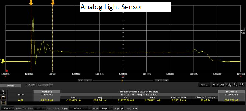
    The sensor controller domain is clocked by the 32 kHz clock during standby when you have set up GPIO event trigger. It takes a few clock cycles for the interrupt to be generated on the chip. During this time the AUX domain is in standby and the current consumption should be in the 1 uA range. Actual wake up and powering of the sensor controller domain (AUX) takes around 150-200 us. I did a measurement on the analog light sensor example (see bottom). This code implement a 1 ms delay during execution.

    2)

    When the sensor controller domain is active there is a baseline current of about 500 uA (due to clocks, power, retention etc). When the processor is running you need to add the processor current as well (8.2 uA/MHz).

    3)

    The power down sequence takes a little more than 100 us as well as seen in the measurement below. Your code will automatically switch back to 32 kHz from 24 MHz when entering standby, while in the example below only 24 MHz is sourced as clock to the sensor controller domain during active mode. The analog light sensor example use the RTC scheduling for wake up and hence does not use any clock while in standby.

    Please note that this was a basic measurement done on my desk on a dev kit and there might be some small discrepancies or inaccuracies. 

  • A Ti-design project has been completed and uploaded to Ti-design web on Dec 2015, project title as"Flow Measurement Reference Design with Reed Switches and BLE".
    or search " TIDM-BLE-REEDMTR" in ti.com.

    This design consumes standby current of 10.3uA in advertising mode and 10.8uA in connection mode.

    The standby current is measured with an advertising signal posting in every time interval of 3.3 second.
    To further lower the current consumption, adjusting the time interval to a longer period will do.

    Best Regards, Thomas Kot