This thread has been locked.

If you have a related question, please click the "Ask a related question" button in the top right corner. The newly created question will be automatically linked to this question.

CC2540 minimal layout design.

Other Parts Discussed in Thread: CC2540, CC2541

Hello,

I am working about a minimal cc2540 configuration. I have designed this schematic for my project: 

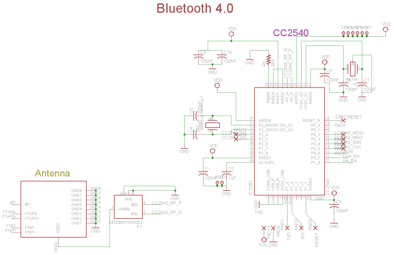
And I have designed the layout like this:

I have tried to connect this one to CCDebugger, and this is not recognized by the CCDebugger (always with red led). 

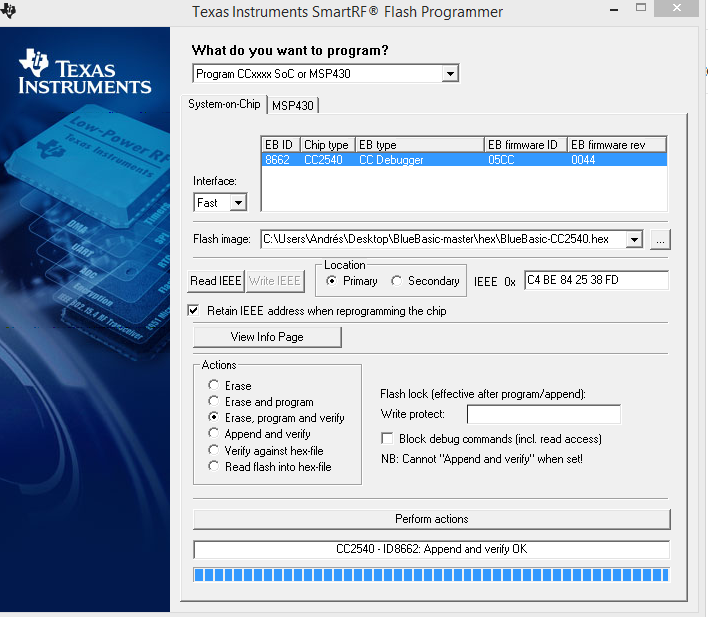
By the way, I have another question, I have tried to program my firmware a commercial cc2540 module with a CCdebuger (with only VDD, GND, DC, DD, Reset), it is recognized and programmed correctly by IAR , but it doesn't show no name, when I scan it with a mobile phone. Can someone help me?

Thanks very much.

  • Not easy to read your pictures, the layout I cannot comment on from the picture. Do you have the pad underneath the chip connected to GND? Your decoupling is not correct, and should be corrected eventhough I do not believe this is causing the issues you are seeing. What is your debug interface to the CC debugger? Both crystals has the wrong load and neither of them will start with todays value. You should also add the filter to the reset_n signal like we have in our reference designs.
  • Sorry, I attach the eagle files.


    I am using pcb with 1 layer and UV sensitive (for this reason ,I want to make the simplest design). I have designed the pcb based to your design check, but it didn't work fine, then I have tried to copy a commercial module (this module is minimal like my design), but it also was not fine. Should I use your design rule ? This design is only a fast test to write a firmware and detect the Bluetooth. The next design will be with 2 layers and good fabrication.

    EDIT: I have used 100pF for the first test, but I have changed for 15pF ( for 32MHz clock) and 10pF (for 32kHz clock). The GND of Thermal Pad is connected to some pins, that are connecte also to GND and the global GND. The CCdebugger is over USB interface.

    bluetooth ver 0.5.rar

    Thanks

  • unfortunately I need gerbers to see your layout. A one layer design sounds risky and I would definitively recommend to follow our reference design and guidelines for your next version. I do not understand what you mean with CCdebugger is over USB interface, the CC debugger must be connected to specific signals on the CC2540 as described on p8 in the ccdebugger user guide www.ti.com/.../swru197h.pdf
  • Hello Charlotte,

    I have remade a new design with all reference design components. It is working fine apparently, It is recognized by the CCdebugger (green light), and I can upload the firmware, but the firmware doesn't work fine. I can't find the Bluetooth with my smartphone. I think it is working the minimal to be recognized by the CCdebugger, but there are some mistake in the design such as the clock or another factor.

    Thanks very much.

    Andres
  • what code are you using? Does your code work on HW from us? Have you checked RF performance by for instant using SmartRF Studio and a spectrum analyzer?
  • Hi Charlotte,

    I have a own firmware, I have tried to load it, (it works fine in the develop board RED BEAR), but it doesn't work, if I load it with RF smart programmer or IAR. If I use the CCLoader firmware with a arduino like a CCdebugger, it works.

    I would like ask if there is some demo binary to test it.
    Have I to program the fuses or a bootloader the very first program?

    Thanks very much.

    Andres
  • Hello Charlotte,

    I have tested a binary found in BlueBasic repository, and I have uploaded the firmware to CC2540 with SmartRF programmer, and it works fine.

    How can I compile and generate the binary file in IAR to be able to upload my firmware? Maybe, I think my problem is I have a wrong options in the binary generation configuration.

    Thanks.
    Andres
  • what example project did you use to program CC2540? Did you use sensortag app or LightBlue to scan your device? IAR can generate hex file or binary file by going to options-->Output Converter--> Generate additional output
  • Hello Christin Lee,

    What is the recommended config to export a .hex / .bin ?

    Thanks.
  • I usually use intel hex output format, but you can just use whatever you prefer. They should all work.
  • Sorry, I am trying to upload the firmware (I attach the .hex file), and it doesn't work.

    I use this connection with my CC2540 board:

    It is recognized by my CCdebugger, and I start SmartRF programmer, and I use this config:


    I click in Perform actions, it works fine, but I can't see the device name, when I scan with mobile.

    It worked fine only one time yesterday, but I can't make it work fine today.

    EDIT: I can't upload .hex file. This is the url repository: https://github.com/aanon4/BlueBasic/tree/master/hex

    Thanks.

    Andres

  • what do you use to scan your device? Do you have sensortag app or light blue app to scan for BLE devices?
  • Yes, I use the official SensorTag of Ti.
  • Hello,


    We have made a new design with all connection pinout for direct connection to ccdebugger. It is working fine, but it load only correctly the BlueBasic firmware, but my Firmware based in Biscuit firmware can't load it. I have a develop board to test it (Ble mini redbear), and this firmware is loaded fine, but the same firmware in my design board it doesn't work fine.

    I don't know, what or where is the problem? I attach the Eagle Cadsoft files (it is made in only one layer, the second layer is used to show the wires in the bottom layer) .

    Thanks.

    Andres

    BLE.rar

  • Please provide gerbers if you want us to look at your layout. 

  • I attach the gerber files.

    BLE gerber.rar

  • Your design is pretty far from our ref design so I assume your RF performance is not optimal. You have routing underneath the balun, the balun is placed a long way from RF pins on the chip, your decoupling grounding is not good, how are that GND plane underneath the chip on the top layer and bottom layer connected to GND? I do not see the vias, but I hope there are many. I assume that the foot print for the antenna is according to the antenna vendor spec. For a small CC2541 design, I recommend looking at the www.ti.com/.../CC2541-POSTAGE-STAMP-RD design for guidance.

    Anyway, I do not completely understand what you are doing now. You say that your FW works with the module from red bear. But not on your HW. Have you tested SW from TI on your HW? Does this work?

    You have stated several CC debugger connections, but if I understand you correctly, you now have at least pin 1, 2, 3, 4 and 7 connected? And that the CC debugger recognize your HW, but it fails to program your HW using SmartRF Flash programmer?

    What is your supply voltage? What is the voltage you measure on Rbias? What is the voltage you measure on the decouple pin? Are the EPG connected to GND and how?
  • Hello Charlotte,

    The central "Thermalpad" of CC2540 is connected to GND, If I load the BlueBasic Firmware to my HW, it works fine (I recognize it with smartphone), but if I load a FW based in Biscuit, it doesn't work fine. Then I tested the BlueBasic in my RedBear board, it works fine, and with my firmware based in Biscuit is working fine.

    Thanks.
  • What is your supply voltage? What is the voltage you measure on Rbias? What is the voltage you measure on the decouple pin? Can you test your hw with SmartRF Studio, does that work?
  • My sypply voltage is 3.3v from CCdebugger, the Rbias voltage is 0.76 - 0.77v and Decouple voltage is 1.73-1.74v. 

    And the smartRF studio is working.

  • The RBIAS voltage should be appr 1.2 V and the DECOUPLE voltage more like 1.8 V so your HW is not working as it should. How is the thermal pad connected to GND? Note that this is not a thermal pad but provides a good RF grounding and is crucial for performance!
  • Hello Charlotte,

    We have replaced the resistor and the capacitor for the correct value, sorry, it was a little error, It give me the correct values in RBIAS and Dcouple pin but it get the same error in the firmware load. I am using the IAR Workbench, but if I use the CCloader (using Arduino as CCdebugger) and load the default demo.bin attached in the repository (firmware of Biscuit to .bin) with size 256KB, it is working, but if I generate my firmware to .bin file (size 104KB) with IAR, and it doesn't work.

    I have thought, maybe it is Software error, the software stores the Device Name to no volatile memory (Eeprom or flash), then it is read by next program and display the old name, then it is not a hardware error, maybe it is only a software error, isn't it? Can you tell me how can I restore the NV memory? There is a Simple firmware to test it from Ti?

    Thanks
    Andres
  • I am not a SW expert, but have you tried one of our SW examples that comes with the BLE stack and seen that they too work on your HW?
  • have you tried to step thru the code with IAR and see where it got stuck? Since you are not using TI example code, it's a bit difficult to support your case. We don't use the code you are using. It's recommended to just use TI example and see if it's works out of box.
  • It is working, it use some eeprom position, and it had a error displaying the device name, but the another values are correct, we are solving this problem.
  • Happy to hear that you are solving this! Have a good week-end!