This thread has been locked.

If you have a related question, please click the "Ask a related question" button in the top right corner. The newly created question will be automatically linked to this question.

CC26xx singularity around Vcc = 1v8

Other Parts Discussed in Thread: CC2640, CC2590

Hi,


My application is likely a home automation application, and I use a CC2640 with its basic configuration (integrated CC-CC converter),


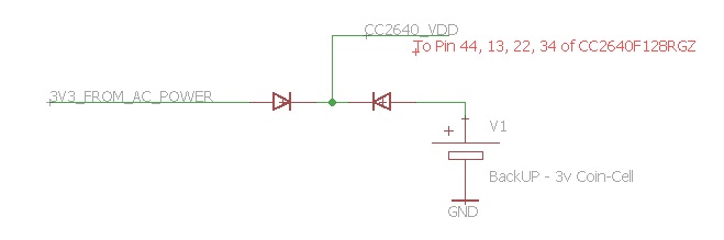
My need is special, because my module has two sources of simultaneous powering.

- The first is a 3v3 AC power.

- The second is a backup powering, it is a 3v coin cell, supplying the module when there is a defect of the first power supply.


 In experimental condition I encounter the following problem:

 When Vcc voltage remains around 1v8,  in this case this is able of generating a crash of the microcontroller.

In this case,  The CC2640 seem to be in particular mode: all IO are not powered, the two crystals oscillators are stopped, the CC-CC regulator not switching but VDDR/VDDRF remains around 1v7. This even if Vcc reach back to 3v3.

The only ways to recover the normal state of microcontroller is that Vcc back down under 1v8 and goes up above 1v8 with a minimal slope, the second way is to asserting hardware Reset signal to ground.


For me because I use the CC2640 with two power supplies, this is a potential problem.

In case if the mains power is off and my backup cell is empty, my backup cell can maintain a voltage Vcc around 1V8. in this case when I recover the 3v3 mains power , I risk not being able to recover a good functionality of microcontroller.


I had read in a specification that this phenomenon  was known  in Standby mode.

In my case I disallow the power saving mode  with the following RTOS command:

"Power_setConstraint(Power_SB_DISALLOW);"

"Power_setConstraint(Power_IDLE_PD_DISALLOW);"


So the only allowed status is Active and Idle.


Is there a way to skirt this problem (changing BOD level or disable it), or other solution from power policy or e-fuse configuration?


In worst case I have a hardware solution to solve this problematic.

  • Hi Damien,

    Note that the lower operation voltage for the CC2640 is 1.8 V, which means that if your supply is hovering around 1.8 V if might go below which will either trigger a BOD or in some cases the behavior you have seen.

    I do not fully understand your power scheme, and how likely this 1.8V operation is. When running off a coin cell, the battery will be dead when the voltage is 1.8 V.

    Cheers,
    Fredrik
  • Hi Frederik,

    Thank you for your prompt response

    My power Scheme is the following one:

    My main power source is the AC Power, The battery is juste a backup power source,
    A dead battery should not prevent the operation of the module when his main power source goes from 'Off' to 'On'

    That is why in my case Vdd of the CC2640 can floating around 1v8 (from dead battery) before he goes up to 3v3 (from main AC power).This can happen when the main power goes from OFF to ON.

    Best Regards.

  • I think it is very unlikely that a coin cell will stay at 1.8 V for a significant amount of time. At that voltage the coin cell is more or less dead and the voltage should fall quite rapidly.

    What you can do is to use the internal battery monitor and disallow the device to enter Standby when the battery voltage falls below 2.0 V for example. Due to what I write above, this should not significantly affect your life time when running off the coin cell.
  • Hi Frederick,

    I think like you.

    So to disallow the device to enter Standby I use the following RTOS commande:
    - "Power_setConstraint(Power_SB_DISALLOW);"
    - "Power_setConstraint(Power_IDLE_PD_DISALLOW);"

    Is it correct? But the problem remains.

    You may be right about the likelihood of this happening.

    It is important for me to properly master this subject.

    Best Regards.

    Damien.
  • Hi Damien,

    The system could be crashed due to power glitch or software bug. In your case, it is more likely power supply issue. I would suggest you to use oscilloscope to monitor CC2640_VDD. In oscilloscope, set a trigger level at 2.2V. It is not reasonable for CC2640_VDD to drop to 2.2V. If this happens then it means your board layout or power integrity is not good enough.
  • Hi rcfocus,


    My board when is powered correctly works really well.
    I have another board with CC2640 and a CC2590/91 and ‘TI’ printed F-inverted antenna, and result is very nice.

    I wanted to take the opportunity to testify to the quality of RF products from Texas Instrument.

    As I mention earlier in this blog, my problem is I have a main AC power (3v3), and in parallel (with diodes) a backup battery (see the diagrams above).

    My problem is, due to my specifications, the backup battery can possibly be dead.


    Also, when AC power is no longer operational, dead battery can cause glitch or voltage around 1v8 on CC2640 VDD, in that case, when the main AC power return, I can't guarantee to recover control of the CC2640.

    My application is like home automation, and I can’t ignore this case in view of the final reliability.

    The solution may be is to trigger a hardware reset on each 'OFF to On' of main AC power.


    In the documentation of CC26xx, it is stated that the area for the 1V8 VDD was not advisable in StandBy Mode, so the solution could have been as advised above by Frederik: prevent the Standby mode when low battery.

    I'd testing this in experimental terms, even by preventing the StandBy mode, the problem persists, sometimes I lose control of CC26540 even after the mains AC power has returned to 'On'.

  • Hi Damien,

    So, the major issue is when backup battery is dead.

    OK, first of all, I won't recommend you to turn off STANDBY mode because it will consume too much current from battery if you keep CC26xx active all the time. The output current of coin cell battery is very very limited.

    One of the method is to use watchdog, when the program is crashed due to out of backup battery, CC26xx will be reset by watchdog and run from start again. But the output voltage of coin cell will drop immediately when there is inrush current. This usually happens when booting up and when RF is activated. So, I will say this is a unreliable way because CC26xx will boot --> crash --> reset --> boot --> crash --> rest... for several rounds.

    An external RESET chip is a very reliable way. CPU like MSP430 has a hardware mechanism to detect VDD, acts like RESET chip. But so far I don't know if CC26xx can do that or not.

    In summary, I would recommend a RESET chip for reliable design.
  • Hi rcfocus,

    Thanks for your advices,
    I will do that.

    Best Regards.

  • This answers my question