This thread has been locked.

If you have a related question, please click the "Ask a related question" button in the top right corner. The newly created question will be automatically linked to this question.

CC2564 Fast Clock Problem

Other Parts Discussed in Thread: CC2564

Hello There,


We are working on a wearable project that uses CC2564-QFN with STM32F411 as Host Controller. We were able to build our application using CC2564QFN-EM and STM32F411 Development board and everything works fine without any issues. Now we have got our designed final proto board and trying to make the application work on our proto board. But unfortunately, we are not able to initialize the Bluetooth module on our proto board.

We have already posted the issue on e2e forum(https://e2e.ti.com/support/wireless_connectivity/bluetooth_cc256x/f/660/t/472007) where we were using Auto sense voltage translator on UART lines and based on your recommendation we replaced that part with the one recommended by TI in the latest  proto board and still the Bluetooth module was unable to initialize..

We tried checking for any errors from design prospective and couldn’t find any as we followed exactly the same design provided by TI.

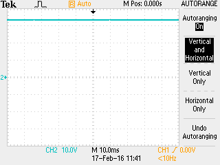
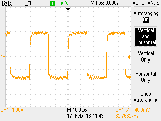
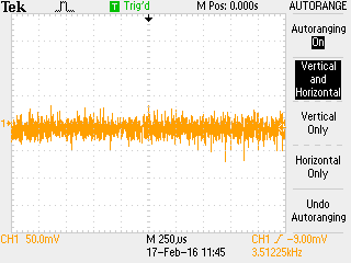
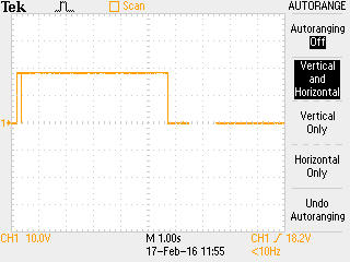
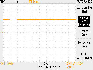
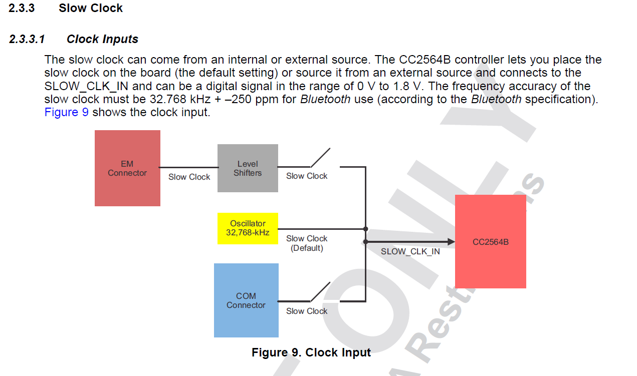
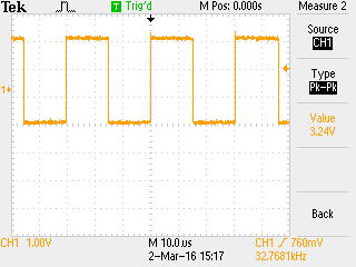
Regarding the clocks, we are getting the accurate slow clock i.e. 32.768kHz from the board and while trying to check the fast clock, we are not getting any signals from the 26MHz crystal. Is there any extra changes to do to make the Fast clock generate signal in terms of Hardware or Software?

We are using CC2564B version chip and service pack version 1.2 that works good with the CC2564-QFNEM development board and it doesn’t generate Fast clock on our Proto Board.

We are in tight schedule as the Mass production deadline is approaching and we need to resolve this issue ASAP to go ahead with Mass production.


Also attaching the schematic of CC2564 on our proto board for your reference.


Thanks.


Best,

Krish

  • Hi,

    As mentioned in the other thread, "Could you send us a screenshot of the initialization sequence? VIO, VBAT, nSHUTD, UART lines, slow clock and XTAL."

    Regards,
    Gigi Joseph.
  • Hi Joseph,

    Thanks for the quick reply.

    We were able to capture the required signals from the oscilloscope. Our Oscilloscope was showing wrong voltage levels but we tested with the multimeter and all the voltages were proper. Don't get confused by the voltage levels on the captured screens from the Oscilloscope.

    Please reply if you need more details from us.

    Thanks,

    Best,

    Krish

    Fig 1: VIO 1.8

    Fig 2: VBAT 3.3

    Fig 3: Slow Clock 32.768kHz

    Fig 4: Fast Clock(Not generating signal)

    Fig 5: NShutDown

    Fig 6: CTS

    Fig 7:  RX

    Fig 8: TX

    Fig 9: RTS(never going low)

  • Hi,

    I have couple of comments:

    a) What is the value of the XTAL caps? Did you follow similar layout design as in the CC2564QFN EM board for this area?
    b) Why is there a glitch on the nSHUTD pin after initialization? How long does it remain low before going high again? See www.ti.com/.../specifications
    c) There seems to be no voltage on the UART pins at some point. Do you know the reason for those gaps?

    Regards,
    Miguel
  • Dear Miguel,

    Thanks for the reply.

    please find the answers to your questions below

    a) What is the value of the XTAL caps? Did you follow similar layout design as in the CC2564QFN EM board for this area?

    Originally the values of CAPS were rated at 12pF, then we tried with 10pF for which we calculated using the load capacitance formula. Also we tried with 8pF and 15pF.     

    Yes , we have followed similar layout design as in the CC2564QFN EM board. We also followed the rules that were mentioned in the CC2564 datasheet and also on the checklist provided by TI

    b) Why is there a glitch on the nSHUTD pin after initialization? How long does it remain low before going high again? See www.ti.com/.../specifications

    The glitch is coming whenever the reset button is pressed which is connected to micro controller. NSTUD will remain low until the reset button is pressed again

    c) There seems to be no voltage on the UART pins at some point. Do you know the reason for those gaps?

    The gap that we see on the screen is because of time scaling of oscilloscope to 1 second.


    Thanks.

    Best,

    Krish

  • Hi Krish,

    Regarding the UART TX pin, I don't understand why there should be gaps (indicating low and high transitions). If the CC2564 device does not initialize, then this line would always be high, i.e. The CC2564 wont be able to respond to any UART command. If the CC2564 is responding then it means that it was initialize.

    On the RTS line side, there is a LOT of noise. Are you sure there is no IO conflict with the host IOs?

    Regards,
    Miguel
  • Dear Miguel,

    Thanks for the reply.

    Regarding the UART TX pin gap you mentioned, its not functioning like the way you mentioned(low to high transitions). The gap is due to the large time period we are using in that case(1 sec).

    We have tested the development kit in which we were able to get the initialization done properly and able to run Demo apps successfully, we can see the similar gaps in that case as well when the time period is set to (1 sec). If the time period is set in the range of milli seconds, we are not seeing any gaps in both cases.

    Regarding the noise in RTS line, its not because of the conflict with the host IO. The noise is probably due to the probe handling.

    The main issue here is that we are not able to get the clock signal output from the Fast Clock(26MHz) and the Slow Clock  is accurate at 32.768kHz. As we are using the same part(NX2016SA) used by TI in the CC2564QFN-EM for the Fast clock and followed the same design provided by TI. We are able to successfully initialize and run the demo Apps on Development board and not able to initialize the bluetooth module on our proto board(we hope the main reason is that the Fast clock is not generating the clock signals).

    We tried on multiple proto boards and the result is same, the Fast clock is not generating the clock signals.

    Please help us to resolve the issue at the earliest.

    Thanks for your continued support.

    Best,

    Krish.

  • Krish,

    What is the slow clock P/N? Why does the signal seem to go from -1.8V to +1.8V?

    Regards,
    Miguel
  • Hi miguel,

    i'm Nag, Colleague of Krish .Regarding the P/N , we are using oscillator from Abracon part named :- ASH7K-32.768KHZ-T ( digikey link :- www.digikey.com/.../2673405 ), which is the one recommended on the TI CC2564x wiki page. When i checked the signal on oscilloscope, we are turning on auto range mode . In this mode Oscilloscope changes its reference voltage to the average input voltage and default voltage reference will changed be changed to new state.

    Regards
    Nag
  • Hi Nag,

    Thank you for the clarification. But the voltage level still looks strange. It seems that the amplitude is ~3.6V. I noticed in the schematics that the clock is supplied with 1.8V but it does not correlate to the observations in the oscilloscope. Other than this observation, I don't see anything else wrong in the schematics. We would need to look at the layout after this.

    Regards,
    Miguel
  • Hi Miguel ,

    I am very happy to tell you that , we were able to root down the problem which caused the CC2564B which is on board to work properly. The problem was with the 32.768kHz oscillator , in that - the voltage which we were giving was 1V8 . What we did is that we took the 32.768kHZ signal from development kit and we gave that to our board CC2564B got initialized and working in no time. When i checked the schematic input voltage for the oscillator in CC2564B datasheet and reference schematic , it was given as 1V8 , but when i checked the development kit and the STADAPT schematic , the input for oscillator was given as VCC_BAT . This change made us to try with the input voltage for oscillator as 3V3 , where CC2564B started working. Why is there a change of voltage given in datasheet and development kit are different. Help us to understand more.

    Thanks for constant support.

    Regards
    Naganand
  • Hi Naganand,

    I am happy that you solved your problem.

    Regards,
    ~Miguel
  • Dear Miguel,

    Thanks for the response.

    We just need clarification regarding the input voltages that was supplied to the Slow Clock(32.768kHz). As per the schematics TI was recommending 1.8V input to the Slow Clock which was not working in our case and when we supplied 3.3v to the Slow Clock, Bluetooth was able to initialize and everything worked properly.

    Can you please clarify regarding the proper usage of input voltage to the Slow Clock. whether it is 1.8v (as per TI) where blue tooth module was not initializing or 3.3v, where blue tooth was initializing and working properly?

    Thank you.

    Best,

    Krish

  • Krish,

    The voltage at the CC256x slow clock pin is 0-1.8V as per the DS. Regarding the CC256xQFNEM board, there is the option to inject a slow clock signal of 0-3.3V if using the EM connectors since there is a voltage translator on the EM board. See below.

    Regards,

    ~Miguel

  • Dear Miguel ,


    Thanks for reply,

    As we tested on the CC2454QFNEM board, the attached image shows the peak to peak voltage as 3.24V. We got this oscillation at pin number 10 i.e SLOW_CLK_EDGEdebug header.

    Please clarify on this.

    Regards

    Naganand V

  • Naganand,

    I checked on my side and I measured 1.8V with the default configuration where the slow clock is supplied thru the EM connector. Which is the source and configuration in your side?

    ~Miguel
  • Could please anyone make a statement if the slow clock requires a voltage level of 3V3.

    We cannot get our CC2564BMODA to initialize when using a ASDK2-32.768KHZ-LR-T3 (1V8).