This thread has been locked.

If you have a related question, please click the "Ask a related question" button in the top right corner. The newly created question will be automatically linked to this question.

SimpleBLEPeripheral 2640 custom board/2650DK-- how to observe advertising

Other Parts Discussed in Thread: CC2640, CC2650, CC2541, CC2590, SYSBIOS

Hi,

SimpleBLEPeripheral built successfully and a debug run on the 2650 DK displayed "advertising" on the 

screen. I ran the project as is without changing any default parameter settings (initialAdvertEnable = TRUE).

What will this project output be like on the 2650DK?

I was also able to successfully build SimpleBLEPeripheral to a 4x4 package. Edits were made to main.c

to set the IOC ports that control the power amplifier on our custom board to transmit and receive.

This code is compiling and executing OK.

I am probing PAEN and EN on the scope and I am not seeing any advertising happening. 

Break points in simpleBLEPeripheral.c are not being executed. Can you offer pointers

here?

Thanks,

Priya

  • We are using an XDS200 debugger with our custom CC2640 board.

    The target config file is set to CC2650 built for a 4x4 package I used the

    same board.c file that came with the CC2650DK.

    I successfully built the SimpleBLEPeripheral to our custom target this way. 

    When I debug this project, here is what I see after PIN_init(BoardGpioInitTable);

    is executed. 

    Expression x = *(PIN_init); type unknown; Value 0x00001988 Error cannot be

    loaded from nonprimitive location.

    What does this error mean?

    Priya

  • Hello Priya,

    For running on 4x4, did you follow the procedure to change to the CC2650EM_4XS board file? This is needed, among other reasons, to get the correct RF settings. See 6.2 Board File in the CC2640 SW Dev Guide (SWRU393).

    Best wishes
  • Yes, I am currently picking the CC2650EM_4XS board file. I did but a break point after the PIN_Init
    function call in main.c and the debugger is complaining about something when I hover over this
    function call. I posted about this on a new thread today. Maybe its related to this issue?
    Thank you for your reply,
    Priya
  • Hello Priya,

    Let's consider them related. I see some new information: you are using a custom board and not the CC2650EM_4XS module. Can you confirm that your board file PIN structure matches your custom HW layout? If not, you can expect to see some undefined behavior.

    For debugging, try removing optimization on the main.c & board.c files.

    Also, if possible, please attach your schematic & board.c/h PIN table.

    Best wishes
  • /*
     * Copyright (c) 2015, Texas Instruments Incorporated
     * All rights reserved.
     *
     * Redistribution and use in source and binary forms, with or without
     * modification, are permitted provided that the following conditions
     * are met:
     *
     * *  Redistributions of source code must retain the above copyright
     *    notice, this list of conditions and the following disclaimer.
     *
     * *  Redistributions in binary form must reproduce the above copyright
     *    notice, this list of conditions and the following disclaimer in the
     *    documentation and/or other materials provided with the distribution.
     *
     * *  Neither the name of Texas Instruments Incorporated nor the names of
     *    its contributors may be used to endorse or promote products derived
     *    from this software without specific prior written permission.
     *
     * THIS SOFTWARE IS PROVIDED BY THE COPYRIGHT HOLDERS AND CONTRIBUTORS "AS IS"
     * AND ANY EXPRESS OR IMPLIED WARRANTIES, INCLUDING, BUT NOT LIMITED TO,
     * THE IMPLIED WARRANTIES OF MERCHANTABILITY AND FITNESS FOR A PARTICULAR
     * PURPOSE ARE DISCLAIMED. IN NO EVENT SHALL THE COPYRIGHT OWNER OR
     * CONTRIBUTORS BE LIABLE FOR ANY DIRECT, INDIRECT, INCIDENTAL, SPECIAL,
     * EXEMPLARY, OR CONSEQUENTIAL DAMAGES (INCLUDING, BUT NOT LIMITED TO,
     * PROCUREMENT OF SUBSTITUTE GOODS OR SERVICES; LOSS OF USE, DATA, OR PROFITS;
     * OR BUSINESS INTERRUPTION) HOWEVER CAUSED AND ON ANY THEORY OF LIABILITY,
     * WHETHER IN CONTRACT, STRICT LIABILITY, OR TORT (INCLUDING NEGLIGENCE OR
     * OTHERWISE) ARISING IN ANY WAY OUT OF THE USE OF THIS SOFTWARE,
     * EVEN IF ADVISED OF THE POSSIBILITY OF SUCH DAMAGE.
     */
    
    /*
     *  ====================== Board.c =============================================
     *  This file is responsible for setting up the board specific items for the
     *  SRF06EB with the CC2650EM_4XS board.
     */
    
    
    /*
     *  ====================== Includes ============================================
     */
    #include <inc/hw_memmap.h>
    #include <inc/hw_ints.h>
    #include <driverlib/ioc.h>
    #include <driverlib/udma.h>
    #include <xdc/std.h>
    #include <xdc/runtime/System.h>
    #include <ti/sysbios/family/arm/m3/Hwi.h>
    #include <ti/sysbios/family/arm/cc26xx/Power.h>
    #include <ti/sysbios/family/arm/cc26xx/PowerCC2650.h>
    #include <ti/drivers/PIN.h>
    #include "Board.h"
    
    /*
     *  ========================= IO driver initialization =========================
     *  From main, PIN_init(BoardGpioInitTable) should be called to setup safe
     *  settings for this board.
     *  When a pin is allocated and then de-allocated, it will revert to the state
     *  configured in this table.
    */
    PIN_Config BoardGpioInitTable[] = {
    
        Board_KEY_SELECT | PIN_INPUT_EN  | PIN_PULLUP | PIN_HYSTERESIS,                             /* Button is active low          */
        Board_UART_TX    | PIN_GPIO_OUTPUT_EN | PIN_GPIO_HIGH   | PIN_PUSHPULL,                     /* UART TX pin at inactive level */
        PIN_TERMINATE                                                                               /* Terminate list                */
    };
    /*============================================================================*/
    
    /*
     *  ============================= UART begin ===================================
    */
    #if defined(__TI_COMPILER_VERSION__)
    #pragma DATA_SECTION(UART_config, ".const:UART_config")
    #pragma DATA_SECTION(uartCC26XXHWAttrs, ".const:uartCC26XXHWAttrs")
    #endif
    
    /* Include drivers */
    #include <ti/drivers/UART.h>
    #include <ti/drivers/uart/UARTCC26XX.h>
    
    /* UART objects */
    UARTCC26XX_Object uartCC26XXObjects[CC2650_UARTCOUNT];
    
    /* UART hardware parameter structure, also used to assign UART pins */
    const UARTCC26XX_HWAttrs uartCC26XXHWAttrs[CC2650_UARTCOUNT] = {
        {    /* CC2650_UART0 */
            .baseAddr = UART0_BASE,
            .intNum = INT_UART0,
            .powerMngrId = PERIPH_UART0,
            .txPin = Board_UART_TX,
            .rxPin = Board_UART_RX,
            .ctsPin = PIN_UNASSIGNED,
            .rtsPin = PIN_UNASSIGNED
        },
    };
    
    /* UART configuration structure */
    const UART_Config UART_config[] = {
        { &UARTCC26XX_fxnTable, &uartCC26XXObjects[0], &uartCC26XXHWAttrs[0] },
        { NULL, NULL, NULL }
    };
    /*
     *  ============================= UART end =====================================
    */
    
    /*
     *  ============================= UDMA begin ===================================
    */
    /* Place into subsections to allow the TI linker to remove items properly */
    #if defined(__TI_COMPILER_VERSION__)
    #pragma DATA_SECTION(UDMACC26XX_config, ".const:UDMACC26XX_config")
    #pragma DATA_SECTION(udmaHWAttrs, ".const:udmaHWAttrs")
    #endif
    
    /* Include drivers */
    #include <ti/drivers/dma/UDMACC26XX.h>
    
    /* UDMA objects */
    UDMACC26XX_Object UdmaObjects[CC2650_UDMACOUNT];
    
    /* UDMA configuration structure */
    const UDMACC26XX_HWAttrs udmaHWAttrs[CC2650_UDMACOUNT] = {
        { UDMA0_BASE, INT_UDMAERR, PERIPH_UDMA },
    };
    
    /* UDMA configuration structure */
    const UDMACC26XX_Config UDMACC26XX_config[] = {
        {&UdmaObjects[0], &udmaHWAttrs[0]},
        {NULL, NULL},
    };
    /*
     *  ============================= UDMA end =====================================
    */
    
    /*
     *  ========================== SPI DMA begin ===================================
    */
    /* Place into subsections to allow the TI linker to remove items properly */
    #if defined(__TI_COMPILER_VERSION__)
    #pragma DATA_SECTION(SPI_config, ".const:SPI_config")
    #pragma DATA_SECTION(spiCC26XXDMAHWAttrs, ".const:spiCC26XXDMAHWAttrs")
    #endif
    
    /* Include drivers */
    #include <ti/drivers/spi/SPICC26XXDMA.h>
    
    /* SPI objects */
    SPICC26XX_Object spiCC26XXDMAObjects[CC2650_SPICOUNT];
    
    /* SPI configuration structure, describing which pins are to be used */
    const SPICC26XX_HWAttrs spiCC26XXDMAHWAttrs[CC2650_SPICOUNT] = {
        {   /* SRF06EB_CC2650_SPI0 */
            .baseAddr = SSI0_BASE,
            .intNum = INT_SSI0,
            .defaultTxBufValue = 0,
            .powerMngrId = PERIPH_SSI0,
            .rxChannelBitMask = 1<<UDMA_CHAN_SSI0_RX,
            .txChannelBitMask = 1<<UDMA_CHAN_SSI0_TX,
            .mosiPin = Board_SPI0_MOSI,
            .misoPin = Board_SPI0_MISO,
            .clkPin = Board_SPI0_CLK,
            .csnPin = Board_SPI0_CSN
        },
        {   /* SRF06EB_CC2650_SPI1 */
            .baseAddr = SSI1_BASE,
            .intNum = INT_SSI1,
            .defaultTxBufValue = 0,
            .powerMngrId = PERIPH_SSI1,
            .rxChannelBitMask = 1<<UDMA_CHAN_SSI1_RX,
            .txChannelBitMask = 1<<UDMA_CHAN_SSI1_TX,
            .mosiPin = Board_SPI1_MOSI,
            .misoPin = Board_SPI1_MISO,
            .clkPin = Board_SPI1_CLK,
            .csnPin = Board_SPI1_CSN
        }
    };
    
    /* SPI configuration structure */
    const SPI_Config SPI_config[] = {
        /* SRF06EB_CC2650_SPI0 */
        {&SPICC26XXDMA_fxnTable, &spiCC26XXDMAObjects[0], &spiCC26XXDMAHWAttrs[0]},
        /* SRF06EB_CC2650_SPI1 */
        {&SPICC26XXDMA_fxnTable, &spiCC26XXDMAObjects[1], &spiCC26XXDMAHWAttrs[1]},
        {NULL, NULL, NULL},
    };
    /*
     *  ========================== SPI DMA end =====================================
    */
    
    /*
     *  ========================== Crypto begin =======================================
     *  NOTE: The Crypto implementaion should be considered experimental and not validated!
    */
    /* Place into subsections to allow the TI linker to remove items properly */
    #if defined(__TI_COMPILER_VERSION__)
    #pragma DATA_SECTION(CryptoCC26XX_config, ".const:CryptoCC26XX_config")
    #pragma DATA_SECTION(cryptoCC26XXHWAttrs, ".const:cryptoCC26XXHWAttrs")
    #endif
    
    /* Include drivers */
    #include <ti/drivers/crypto/CryptoCC26XX.h>
    
    /* Crypto objects */
    CryptoCC26XX_Object cryptoCC26XXObjects[CC2650_CRYPTOCOUNT];
    
    /* Crypto configuration structure, describing which pins are to be used */
    const CryptoCC26XX_HWAttrs cryptoCC26XXHWAttrs[CC2650_CRYPTOCOUNT] = {
        {CRYPTO_BASE, INT_CRYPTO, PERIPH_CRYPTO}
    };
    
    /* Crypto configuration structure */
    const CryptoCC26XX_Config CryptoCC26XX_config[] = {
        {&cryptoCC26XXObjects[0], &cryptoCC26XXHWAttrs[0]},
        {NULL, NULL}
    };
    
    /*
     *  ========================== Crypto end =========================================
    */
    
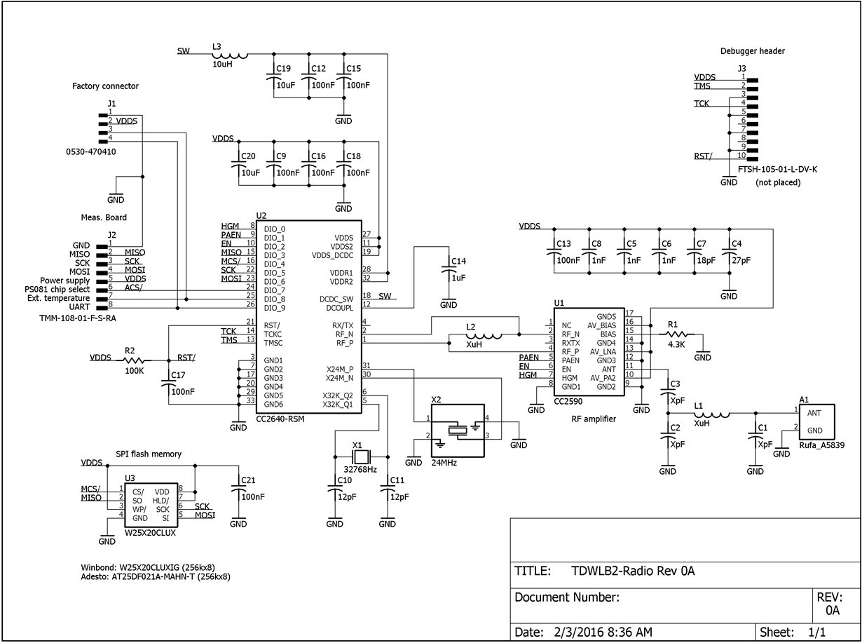
    4744.Board.hI have attached the schematic for this custom board. The Board.c and Board.h are the 

    same as the CC2650_4XS files that came with the CC2650DK.
    Thank you,
    Priya
     

  • Hello,

    Since you are setting the IO pins directly via IOCPortConfigureSet , you should take them out of the BoardGpioInitTable as you will have a conflict.

    Best wishes
  • JXS--
    The only 3 pins I am currently defining through IOCPortConfigureSet are what the RF Power Amplifier needs. (HGM, PAEN and EN).

    The PIN table in the board.c file has the same code as from the 2650DK:
    PIN_Config BoardGpioInitTable[] = {

    Board_KEY_SELECT | PIN_INPUT_EN | PIN_PULLUP | PIN_HYSTERESIS, /* Button is active low */
    Board_UART_TX | PIN_GPIO_OUTPUT_EN | PIN_GPIO_HIGH | PIN_PUSHPULL, /* UART TX pin at inactive level */
    PIN_TERMINATE /* Terminate list */
    };

    Which part of this table can I remove?

    Should I be making specific IOCPortconfigureSet calls for the SPI and UART pins for the custom board?

    I don't understand how to edit this BoardGPIOInitTable clearly.

    Thanks,
    Priya
  • Priya,

    The BoardGPIOInitTable is just an array of structures, with each element corresponding to the respective pin (mapped via board.h).

    #define Board_UART_TX IOID_2 /* RF1.9 */
    is the same pin as your EN in your schematic, so you shoudl remove this line from your BoardGPIOInitTable .

    If you are using the PIN driver to access a giving DIO / pin, then add them to the table. If you use the IOC driverlib module, then do not use the table.

    I would suggest that you go through the board file and make sure it matches your schematic.

    Best wishes
  • Without reading the entire thread, some comments to your schematics. You must configure the CC2640 to a differential front-end with internal bias. L2 should be not mounted. For the CC2590 part (decoupling and ant pin) you should copy the CC2541 CC2590 reference design, see www.ti.com/.../cc2541-cc2590em-rd. And you will most likely need placeholders for antenna tuning.
  • Charlotte-- L2 is only a placeholder on the schematic, it is not on our layout board. The CC2541 CC2590 

    was the reference design used to get started. Thanks.

    JXS-- thank you for the feedback. I have made edits to the board.h file to match the pins on our schematic.

    1. I removed IOs for LEDs, there are none on our custom board.

    2. I left the KEY_SELECT_IOID7 in place. Our schematic will be using this IO for

    a different purpose, not currently part of the board being programmed, though it will

    eventually have a different name.

    3. I re-numbered the UART and SPI pin definitions to match the schematic.

    Not much has changed in the debug run, build is successful. If you happen to notice

    anything else, I appreciate a reply. I will keep looking for more.

    Thanks,

    Priya

    /* Mapping of pins to board signals using general board aliases
    * <board signal alias> <pin mapping>
    */
    /* Leds */
    #define Board_LED_ON 1 /* LEDs on CC2650 are active high */
    #define Board_LED_OFF 0
    #define Board_LED1 PIN_UNASSIGNED
    #define Board_LED2 PIN_UNASSIGNED
    /*#define Board_LED3 IOID_5 */ /* RF1.2 */
    /*#define Board_LED4 IOID_6 */ /* RF1.4 */
    /* Button Board */
    #define Board_KEY_SELECT IOID_7 /* RF1.14 */
    /*#define Board_KEY_UP IOID_4 */ /* RF1.10 */
    /*#define Board_KEY_DOWN IOID_3 */ /* RF1.12 */
    #define Board_KEY_LEFT PIN_UNASSIGNED
    #define Board_KEY_RIGHT PIN_UNASSIGNED
    /* LCD Board */
    #define Board_3V3_EN PIN_UNASSIGNED
    #define Board_LCD_MODE PIN_UNASSIGNED
    #define Board_LCD_RST PIN_UNASSIGNED
    #define Board_LCD_CSN PIN_UNASSIGNED
    /* UART Board */
    #define Board_UART_RX IOID_9 /* RF1.7 */
    #define Board_UART_TX IOID_8 /* RF1.9 */
    #define Board_UART_CTS PIN_UNASSIGNED
    #define Board_UART_RTS PIN_UNASSIGNED
    /* SPI Board */
    #define Board_SPI0_MISO IOID_3 /* RF1.20 */
    #define Board_SPI0_MOSI IOID_6 /* RF1.18 */
    #define Board_SPI0_CLK IOID_5 /* RF1.16 */
    #define Board_SPI0_CSN IOID_4 /* RF1.14 */

  • Here is one more thing I noticed:
    Under the PIN26CCXX.c in SimpleBLEPeripheral in my project workspace,
    the following files show up with a yellow exclamation point:
    BIOS.h
    Power.h
    PowerCC2650.h
    Hwi.h
    Semaphore.h

    What might this mean? When I debug this project, everything looks fine
    when I hover over BoardGPIOInitTable. Its only when I hover over PIN_init,
    I see the "Error cannot be loaded from nonprimitive location."

    Thanks,
    Priya
  • I have implemented everything discussed here and from this answered thread from a year ago:
    e2e.ti.com/.../406173

    What I did notice is the version of BLE stack I'm using is different than what worked for the custom board a year ago.
    (BLE stack 2.1.1.44627). The RTOS version, CC26XX ware etc are all what were installed by this version of the stack.
    Maybe there is some change needed to this? Any fresh pointers are appreciated.

    Priya
  • After adding init statements for all the used ports of the CC2640 in the BoardGpioInitTable, the IOC
    ports are initializing as expected.

    I am able to set a break point at Task_construct(&gapRoleTask, gapRole_taskFxn, &taskParams, NULL); inside GAPRole_createTask. After which the debugger does not resume any more. Task_Construct seems to be a sysbios kernel task, is something wrong with the RTOS kernel in our set up?

    Thanks,
    Priya
  • To add to my previous post, the CC2650DK is advertising and connecting fine for both the 7x7 and 4x4 packages. The question is, why is our custom board having difficulty constructing the gap role task. Are there parameters that need setting we're missing? Your help is much appreciated.
    Priya
  • The custom board is now working through CCS as well! All along, the connector to the XDS200 debugger could connect in two ways and it got hooked the wrong way every time SPB run was tried. Until we flash programmed the hex files, we couldn't track it down to this seemingly small error. I appreciate all the insight and help.
    Priya