This thread has been locked.

If you have a related question, please click the "Ask a related question" button in the top right corner. The newly created question will be automatically linked to this question.

CC2640 with external regulator (TPS782) problem

Other Parts Discussed in Thread: CC2640, TPS782, TPS706

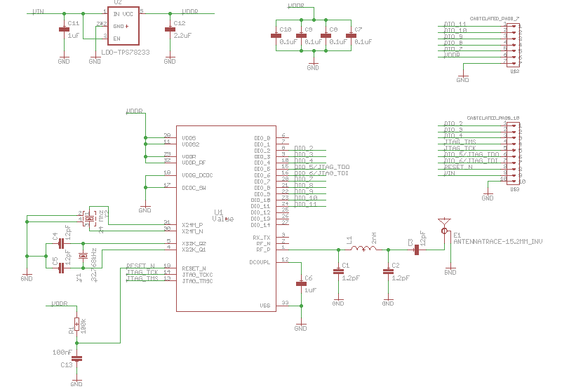
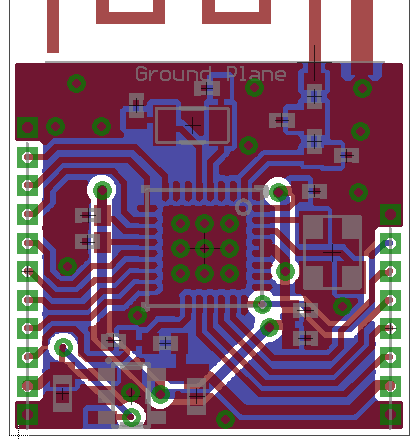
I develop a PCB with the cc2640 (RHB) with single ended and internal bias antenna. For the power configuration i used external regulator because i need to power it from higher voltage than the cc2640 internal dc/dc can handle (>4.2 V). 

For powering the cc2640 i'm using the TSP78218 with ultra low quiescent current: 500nA. 

For the firmware i'm using then SimplePeripherial example. The PCB runs ok and the module advertises and i can connect to it. The problem is that every time i try to discover the services it fails.

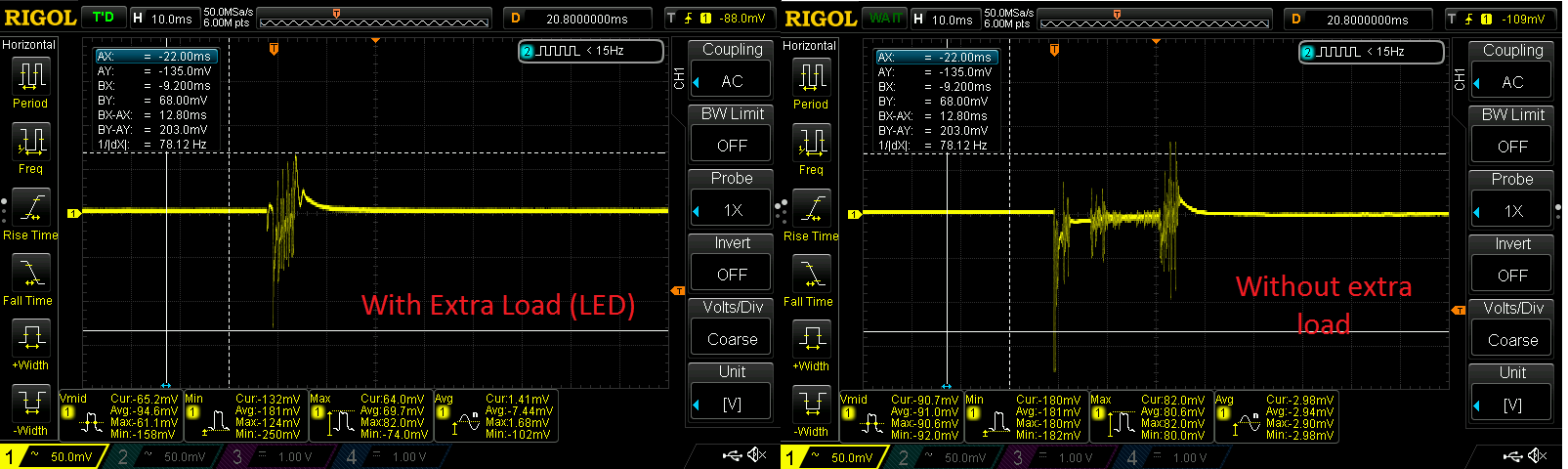
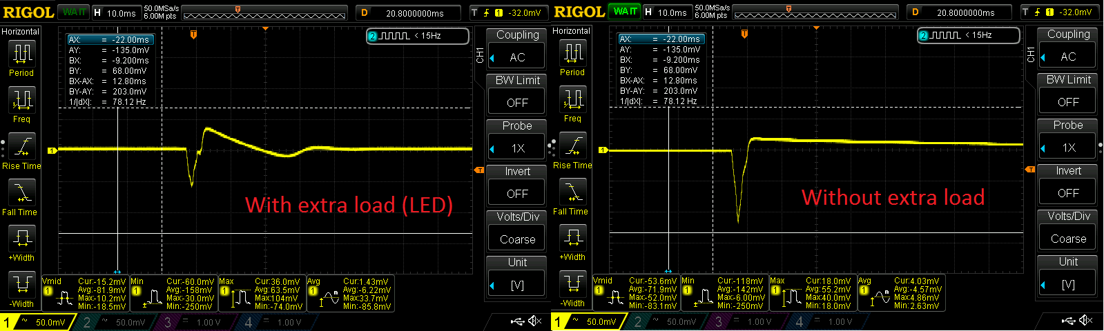
To my surprise after some try and error i found that if i put some load on the 1.8 rail it works (like a led or a 1k resistor). I don't know what may be the problem, but i made 3 boards and one works as is, but the other 2 needs the load.

it means that the TPS782 is failing?, that the change from the ultra low corrent when the cc2640 in idle mode to the relative high current in communication (discover the services) produces the fail? i tried putting a higher capacitor on the regulators output but it keeps failing. Also in the advertising mode it works fine and this mode also have the spikes of current of the advertising brust, so i don't know how to debug it.

Any clue about the problem?

i will buy some TPS706 to try diferent regulators, when they arraive i will put the results.

EDIT:

in link says:

"BLE Connection issues
My device is advertising but fails to connect, what is wrong?
This typically happens if the 32.768kHz crystal is not connected or fails to start up. When the device boots it starts up by using the internal 48MHz RC Oscillator / 1536 as source for the LF system clock, which is used for the RTC. This causes the RTC to tick at 31.25kHz instead of 32.768kHz. When trying to connect the device will consequently wake up too late for the connection event and a supervision timeout will occur.
Add the 32.768kHz crystal and/or make sure the crystal is within the requirements in the CC2640 datasheet. The load capacitors must also be dimensioned correctly to get the crystal to oscillate at the right frequency."

But i can connect to the module, the problem starts when i try to discover the services (From an Android phone)


  • have you tried bypassing/removing your DCDC and used external power? Or tried adding a bead from after the DCDC like in our ref design? How high capacitance did you try?

    Your schematic looks ok, did you disable the DCDC in SW as well? I do not see anything in your layout that I would suspect causing this either. For future versions of the PCB, to improve performance though, you can consider adding antenna tuning components, all RF comp should have separate vias to GND and there should be no routing between decoupling GND vias and the vias under the chip. Also, routing under the crystal traces is not recommended and distance from the RF pins to comp should be kept to a minimum. Also decoupling caps should be placed close to the pin it is to decouple.
  • Also if you could monitor the VDDR voltage that would be useful. And if you are to try several DCDCs, I would recommend the TPS6274x that we used, see www.ti.com/.../swra498.pdf
  • i think i know where the problem is. I used an oscilloscope to measure VDDR as CHS sugested and i obtained the signal when the advertising brust ocurr:

    As you can see when the load is inserted the drop in voltage is less than without load so i think that when the brust ocurrs it drops below the device minimun and the device resets, thats why there are more brusts after the first one (the device is reseting every advertising period!). that don't explains why i can connect to it.

    i put some capacitor extra (10uF) to the TSP782 output but i keeps reseting, so i used a 100uF electrolitic capacitor and it works. Images with 100uF electerolitic capacitor:

    The brust is smaller so it dosen't drops below the limit. 

    Oviusly the 100uF is not the solution, i need a better filter. what do you sugest me to use to minimize the efect of the brust? you said a bead, but i have no experience in this, can you tell me how to choose the right one?

    NOTE: i can't notice the reset in debug mode in the CSS, because the programing board i'm using has a led powered by the module, so it has always a load in the TPS782.

    Thanks for your help.

  • It looks like the transitions between the very low current load to higher current loads cause issues for the LDO. I recommend that you post in the linear regulator forum e2e.ti.com/.../ as they are the experts on these products and will able to support you the best on this topic.
  • I don't think your problem is related to the LOD.

    As I can see, your original circuit will fail without doubt. You should put at least 30uF close to VDDR. And another 10uF for system. Btw, as mentioned by CHS, the trace under crystal is pretty bad. You may encounter unstable issue in reliability test. I would recommend you to do a new layout.

  • Hi Robert,

    The problem was explained and resolved in this thread: e2e.ti.com/.../505958

    Cheers,
    Fredrik
  • Hi Fredrik,

    Thanks for the link. Learned transition issue from the link.

    I always suppose power supply has internal resistance and there is always voltage drop when inrush current is required. And the bulk capacitors are used for the inrush current.