This thread has been locked.

If you have a related question, please click the "Ask a related question" button in the top right corner. The newly created question will be automatically linked to this question.

CC2540 BIM corruption

Other Parts Discussed in Thread: CC2540

Hi,

Over the past year, there are a few instances where one of our CC2540 based device fails to beacon.  It does not seem to have any life.  I dumped the flash out and was surprised to find that the BIM had been erased entirely.  There were no issues with the rest of the flash dump. In fact, I just reprogrammed the BIM and the device sprung back to life.

A couple of questions:

  1. What are the possible causes for the BIM getting erased, but not any any other flash sectors?
  2. Is there a way to protect the BIM sector (the first sector) in flash during manufacturing while our hex image is loaded into the device?
  3. For devices that are already out there in the field, is there a way to lock the BIM after an OAD upgrade?
  4. Is there a possibility of the last sector getting erased?  Does this sector need to be explicitly protected too?

I am running BLE Stack 1.4.0.

As always, thanks for your response.

Regards,
KK

  • Hi KK,

    1. It shouldn't happen by itself. Is it related to an OAD operation or does it just randomly happen? It could of course happen if the code goes haywire, due to e.g. stack of heap overflow/corruption.

    2. During manufacture when you program in the entire merged hex image with bim and images you may also set the lock bit for the BIM page(s).

    3. No, unfortunately the last page (with the lock bits) is not changeable by the running image. See SWRU191 chapter 3.4/.1 Flash Programmg for question 2 and 3.

    4. No, this can only be erased in debug mode, and the lock bits can only be cleared via a total chip erase command via debug.

    Best regards,
    Aslak

  • Thanks for your quick update.

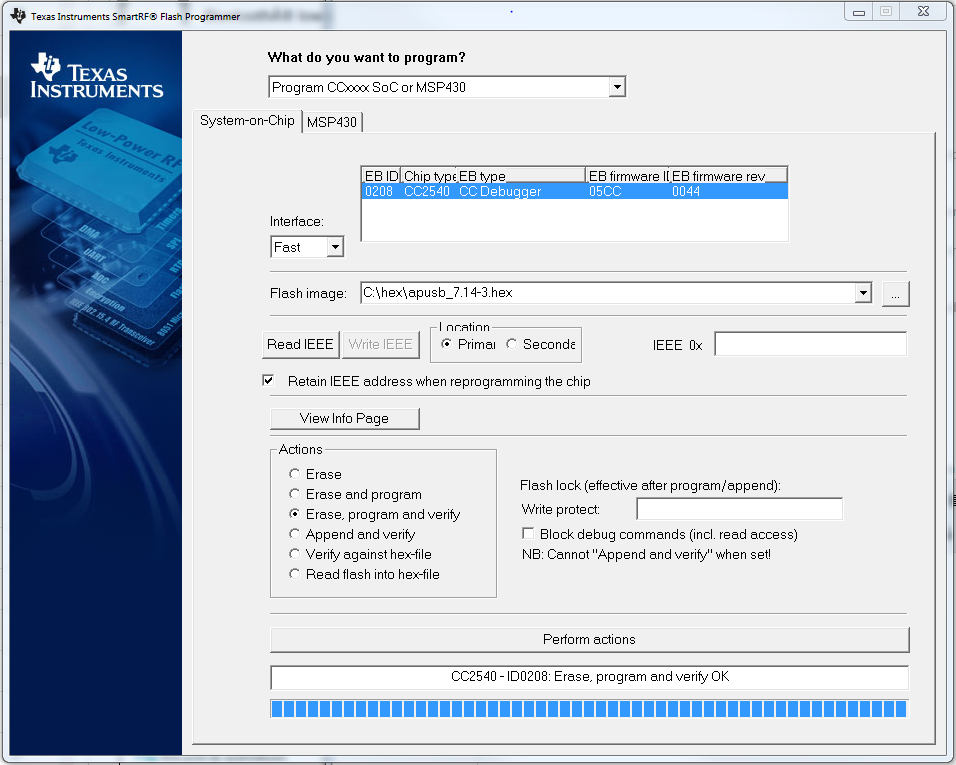
    Shown below is the SmartRF Programmer for the CC2540, UI version,  

     I

    a)  Is the "Write Protect" field where I would protect the BIM sector?

    b) Is the value zero based or one-based.  i..e, should it be 0 or 1 for BIM?  I think it's zero-based and consequently 0 for protecting BIM, but please confirm.

    c) From the command line of SmartRFProgrammer, i.e.,  SmartRFProgConsole.exe, which option achieves the same thing as protecting from the SmartRFProgrammer UI?  Is it LP(0)? (of course, assuming 0 is for protecting BIM)

    I will verify this in code as you suggested in SWRU191 chapter 3.4.

    Regards,
    KK

  • KK said:
    a)  Is the "Write Protect" field where I would protect the BIM sector?
    b) Is the value zero based or one-based.  i..e, should it be 0 or 1 for BIM?  I think it's zero-based and consequently 0 for protecting BIM, but please confirm.


    In the "Write protect" field, you specify the pages you want to protect. For example, if you want to protect page 0 and 2 through 5, you specify

    0,2-5

    KK said:
    c) From the command line of SmartRFProgrammer, i.e.,  SmartRFProgConsole.exe, which option achieves the same thing as protecting from the SmartRFProgrammer UI?  Is it LP(0)? (of course, assuming 0 is for protecting BIM)


    Yes, that's correct. The LP(x-y) option is available for CC253x and CC254x devices. The CLI will print out the documentation if you run SmartRFProgConsole.exe without any arguments. Excerpt:

    LP(x-y)  Write protect flash pages from page x to page y.
             Several ranges can be given separated with a comma:
             E.g. LP(0-26,48-126), LP(0,1,2,8-10).

    Br,
    TIABO

  • Thanks TIABO for your quick response.

    This takes care of it. I programmed the device using "SmartRFProgConsole.exe S EPV F=foo.hex LP(0)".   I was able to verify it by reading back the last page using "SmartRFProgConsole.exe S RP=127 F=read5.bin" .  I saw one bit being flipped to zero, in the last 16 bytes of read5.bin.  If I omitted the LP(0) in the programming command, the bit was a 1.

    Much thanks again.  I would have marked your response as VERIFIED but I don't see the verify button.

    Regards,
    KK

  • Following up on the previous suggested solution, I submitted a request to our manufacturing folks to lock the BIM  area (sector 0 in flash) during the burning of the image into CC2540 flash. While the console version of Smart RF Flash Programmer does indicate that it is locking flash it does not mention which sectors are being locked and this is not pedantic enough for a Mfg person.  I need a reasonably way to validate this after the CC2540 is programmed. Using IAR,  mapping the last flash bank,  and then viewing memory in IAR is way too complicated for the Mfg line.

    Instead I found this to work but wanted to validate with the experts.  

    Step 1) I extract the last sector in Flash using the following command at the DOS prompt in a Windows cmd: SmartRFProgConsole.exe S RP=127 F=Sector_127_lock.bin

    Step 2) I parse the output and look at the first byte at the lock-bits, row 0x000007f0, as shown below, using the command: hexdump -i Sector_127_lock.bin -n | tail -n 2

    Some questions:

    1. The first byte in the lock-bits row is 0xFE.  If I did not lock the first sector it shows up as 0xff.  I assume that since it shows up as 0xfe it implies that the BIM sector is locked.  True?
    2. When I look at the first 0x90 byes using View Info page form Smart RF Flash Programmer, it contains data including the mac address.  However if I were to read the last sector using SmartRFProgConsole.exe, I find that the first 0x90 byes are all 0xff.  Why?

    I would appreciate your input on this.

    Regards,
    KK

  • Hi,

    1. True. The flash lock bits are located in the upper flash sector as you say. Reading 0xFE from address 0x7F0 in your case means sector 0 is locked. More details about the flash lock bits can be found in section 3.4.1 of the CC253x/CC254x User's Guide (swru191).

    2. The reason is that the info page is not the same as the upper flash sector. The CLI does not support reading out the entire info page, but you can read out the primary MAC address stored there using

    RI(F=<file>, PRI)

    option. For more details about available options, run SmartRFProgConsole.exe without any arguments.

    PS. You can explicitly lock flash sectors using the LP(x-y,...) option. It can be combined with programming images.

    Br,
    TIABO