This thread has been locked.

If you have a related question, please click the "Ask a related question" button in the top right corner. The newly created question will be automatically linked to this question.

CC2650 RF-N RF-P is measured identical on scope

Other Parts Discussed in Thread: CC2650, CC2541, CC2640

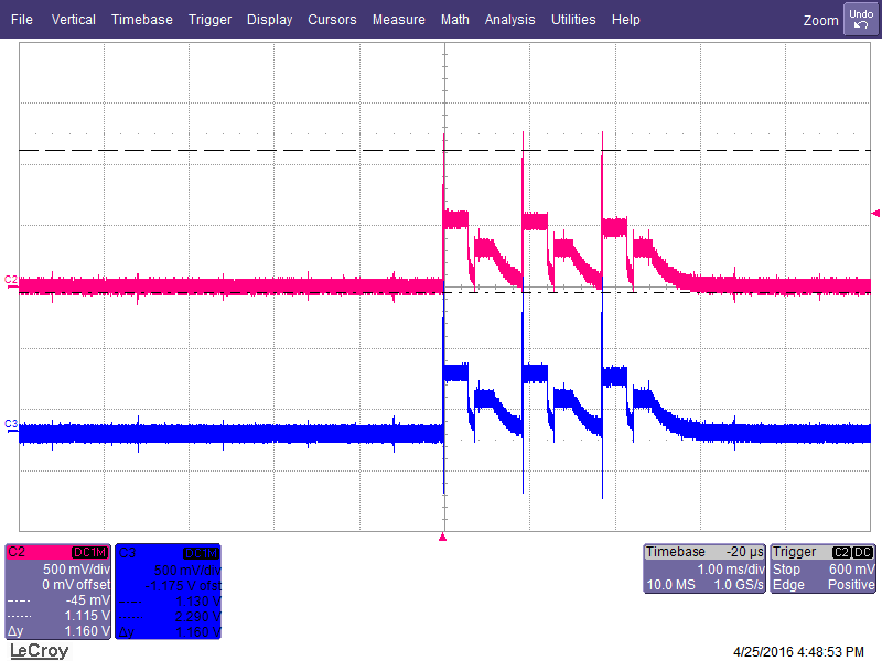
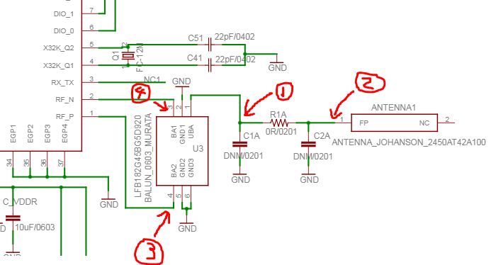
I'm using oscilloscope to measure RF-N and RF-P pin on CC2650 during sensortag operation and found they produce exact same positive RF signal. Should RF-N be negative according to description "Negative RF output signal to PA during TX" to construct a differential signal using RF-N and RF-P? End result is after feed RF-N and RF-P into a balun the output RF signal is 0. Please suggest if there's any FW knob in Sensortag source code to flip RF-N output voltage to negative.  Thanks!

  • Why are you measuring on the RF pins with an oscilloscope? What information are you looking for? What impedance do you have on the pins when doing the measurements? If you let us know more of what you are trying to achieve it will be easier to guide you, because your measurements will not give you the information you are looking for.  Note that an ideal output signal from the RF pins in TX mode is a square wave signal at the RF_P and RF_N pins and a sine wave at the antenna port. To achieve this, the filterbalun must reflect the harmonics back towards the RF_P and RF_N ports. The shape of the square wave pulse depends on the impedance at the different harmonics. The balun has a ±90 degrees phase shift implemented by using a low pass filter and a high pass filter. An unbalance in the balun causes higher harmonic level. Another effect of having an unsymmetrical balun is reduced output power at the single ended side of the balun.

  • Hi Charlotte,

    Thank you so much for your reply. Let me rephrase my issues more clearly. We have a customized board using CC2650-5XD as main chip. Our design relies highly on TI Sensortag2 (both schematic and firmware). After load a sample code "BLESimplePeripheral" into our board, it connected to Sensortag App successfully but only able to maintain connection within roughly 2 meters, means if I move my phone a little further away from my board, the BLE connection automatically dropped and CC2650 resumes to advertising state. The strange part is RSSI signal from sensortag App seems within normal range (-70dB) when connection dropped. We run same code on TI Sensortag2 board and seems don't have this short connection range issue (I was able to maintain connection with Sensortag 2 board for at least 10 meters). 

    Then we are trying to debug the issue. This is why I start to measure RF pins and antennas on our customized board to check if RF signal is healthy. My Oscilloscope is using DC1MOhm coupling(impedance) during measurement. When I check the output signal from RF_N and RF_P pin I can see identical square wave signal that you described coming out from both pin. It triggered every 100ms so I know it is my RF advertising signal. However, I cannot get any RF signal at Balun output pin. If I took the same measurement on Sensortag board, I do get RF signal reading from Coaxial Switch pin. 

    This is the signal I measured at RF_N and RF_P pin.

    This is the signal I measured at balun output, I can't see any RF signal except an amplified noise signal

    This is the signal I measured at Coaxial Switch pin on TI Sensortag 2

    This is our board schematic, the place I took measurement is highlighted

    Thank you! Any idea would be helpful.

    Regards

  • Hi,

    Then I see what you are trying to debug, but measuring with an oscilloscope on the RF pins will not solve this. I see you say you use the 5x5, have you changed the board file in your SW? Also, you say you have CC2650-5XD, but since you use the murata balun, you do not use external bias but internal bias (RXTX pin is not connected). So in your SW, your front-end configuration should be differential with internal bias (ID). Can you verify that this is done correctly in SW? Also, if you can post your RF layout so that we can check that as well?

  • Hi Charlotte

    I am another team member and work with Wei qin for this project. I am providing the hardware layout here.

    I am using CC2650 (5x5mm)-MCU-CC2650F128RHB as the MCU in my project. The way I designed the RF part showing as below:

    Balun: LFB182G45BG5D920TEMP from Murata (refer to CC2650-MurBal Reference Design)

    Antenna: 2450AT42A100, 2.4GHz Antenna from Johanson Technology (refer to CC2541 stamp reference design.)

    Trace from the balun output (unbalance port) to the antenna’s feeding point is 50 ohm (specified when manufacturing my board).

    The big problem here is: when I use TI sensortag App to check the Bluetooth signal, the signal will be disconnected in only 3 meters’ distance (nothing blocks it in between my phone and my PCB)!

    BLE supposes to support 10-15 meters connection.

    I attached my PC board layout.

    U1 is the MCU CC2650, U3 is the balun. R1A is 0 ohm, C1A and C2A are DNM (do not mount).

    Could anyone give me some suggestions regarding to debug this Bluetooth issue? Where could possibly be the issue? I thought I already took care of all the matching here, from MCU’s RF_N and RF_P to Balun, Balun to trace, trace to Antenna. They are all 50 ohm matching. What else could be causing this critical failure?

    I am looking forward to hearing anything back as soon as possible.

    Thanks a lot.

    Best regards

    Fu

  • It is hard to comment on your layout without seeing the GND planes both on the top layer and the layer underneath. From what I see, your design is not similar to our reference design at all. Why do you have the RF traces going through different layers, the traces and vias will increase the inductance. It is recommended to keep all RF comp, crystals and decoupling caps on the same layer as the cc2640. Do you have a GND layer on the top layer and the layer underneath the device? Have you looked at the layout advices on our wiki

    You are correct that the performance on your board is very poor and can be improved. If you send me a friend request, you can send me the gerbers off the web and I can give you more feed back on your design. 

  • Hi Charlotte

    I double checked my FW and found issue was caused by wrong bias setting. After I change bias to internal issue resolved. Thank you very much for your patient guide and help!