This thread has been locked.

If you have a related question, please click the "Ask a related question" button in the top right corner. The newly created question will be automatically linked to this question.

Failure to construct task in the Peripheral example project. URGENT, HELP PLEASE!

Other Parts Discussed in Thread: BLE-STACK

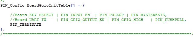
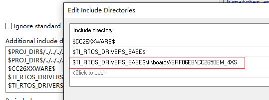
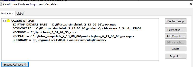
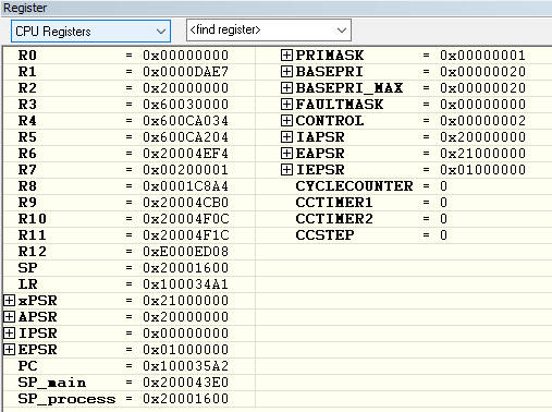
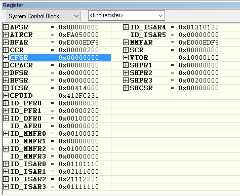
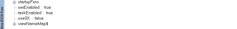
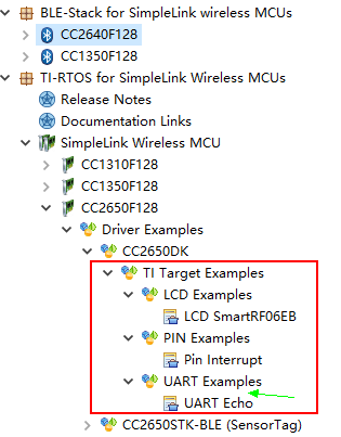
My CC2640RSM board is based on the 2650EVM_4XS design. I tested it with the Peripheral example project. The board file and the preprocessor setting are modified accordingly and both the stack and application program were successfully downloaded into the chip. But during debugging, I found that it failed to construct the task. Every time the program runs to the "Task_construct(&sbpTask, SimpleBLEPeripheral_taskFxn, &taskParams, NULL)", I try to Step Into the function but it would just jumps out and to the BIOS_start() function, haven't been able to reach the SimpleBLEPeripheral_init() function. I saw from the Assembly window that it jumps from the address of 0x82e2 to 0x82ee:

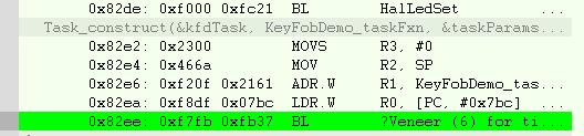
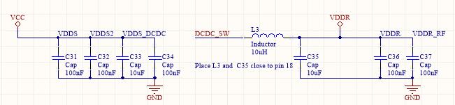
What might be the cause of this problem? Since the program can be successfully downloaded and the chip is able to control an led as programed, the JTAG part should be fine. I have tested all the power supplies and they all meet the specification requirement:

The 32khz & 24Mhz crystals and the antenna are not involved until the task is constructed, right?

Is this a software or hardware problem? I am sort of out of ideas now and desperately need help, please!

The relevant schematic part and the PCB layout are attached for better reference:

1/POWER SUPPLY

2/MCU

 \

3/ ANTENNA (SINGLEENDDED)

4/PCB

I have tried to erase the chip and re-download the program but it does not change anything.

Any help will be much appreciated!!!

  • Hello,

    Your description doesn't match the screen shots of the task construct debug session (e.g., you describe using SBP but the snapshot shows keyfob demo), so I suspect there are other variables that need to be accounted for but not described in your OP.

    Please take the the BLE-Stack v2.1.1 SBP project, change the board file include path to pick up the CC2650EM_4XS board file (as per guidance in the SW Dev Guide SWRU393), disable the LCD and SPI drivers in the App project settings. Next, remove all pins from your BoardGpioInitTable so that just PIN_TERMINATE is listed.

    Also, I recommend disabling optimization for the files you intend to single-step with the debugger.

    With the above changes, the SW, when built & programmed according to the instructions, should function w/o needing any external IO configurations.

    Best wishes
  • Hi JXS,

    Oh I attached the wrong snapshot. I ran both the peripheral and the modified keyfob project on my custom board and the same problem exit: it could not enter the  taskFxn().

    As you suggested, I took the BLE-STACK v2.1.1 SBP project, changed the board file and included the path to pick it up, and disabled the LCD and SPI drivers:

    However, the program was still not able to enter the taskFxn().


    I ve set the Code Optimization level to the lowest, but I cannot single step into the TaskFxn(). I can only see it ran in the Disassembly window. 

    does this have anything to do with the external crystals and the antenna, that for example, it is possibly caused by the malfunction of the external 32kHz crystal? Or it might have to do with the stack configuration (I made no change to the stack)?

    I try to map the 32khz LF clock to a chosen DIOn with the following two driverlib calls, which are added into the SBP.c:

    IOCPortConfigureSet(Board_LED1, IOC_PORT_AON_CLK32K, IOC_STD_OUTPUT);
    AONIOC32kHzOutputEnable();

    But when making, error occurs indicating no definition of AONIOC32kHzOutputEnable(). Do I have to include any additional lib other than the existing ones included in the SPB.c?

    By the way, sometimes during debugging, warnings like this occur. Is that normal?

    I have been stuck on this problem for many days now~ your help is much appreciated!

    Shuting

  • You have to include aon_ioc.h and ioc.h from driverlib into where you use those function calls, as shown below:
    #include <driverlib/aon_iocc.h>
    #include <driverlib/ioc.h>

    Can you also checkout if disable power_saving will make the application run on your device?
  • Hi Christin,

    I deleted the POWER_SAVING in the defined symbol and disabled the related code in the main.c.

    But still, nothing change.

    I included the driverlib files, but when making, an error occurs: cannot open source file "diverlib/aon_iocc.h". this is my Custom Argument Variables setting:

  • Hi,

    You should not delete the Power_setConstraint part of code in the main.c. The purpose of deleting POWER_SAVING from the predefined symbol is that in the main.c if the program sees that POWER_SAVING is not defined, therefore device does not go to sleep.

    Also you have typo in diverlib/aon_iocc.h --> should be driverlib/aon_ioc.h
  • Hi Christin,

    Oh, that was a silly mistake~...I corrected it but the it still could not enter the TaskFxn().

    I mapped the external LF clock to a DIO, and this is the output:

    The frequency is 32.7739kHz, which is out of the allowable range (<500ppm), right? Would this be a problem? Because I also measured the LF clock output on my other developing board (7ID), which works fine. And its output frequency is 32.7729 khz.

    BR

    shuting

  • Hi there,

    Can you follow the steps in Chapter 9 of the Software Developer's guide under Deciphering CPU exceptions and take screenshots of the registers and ROV at the time of failure?

  • Hi Sean,

    I noticed that when the program runs to the BIOS_start() function, the TI-RTOS->Task->basic subview shows that the mode of the SimpleBLEPeripheral_taskFxn is ready. But when I single step into the BIOS_start(), which is supposed to reach SimpleBLEPeripheral_init(), instead it seems to enter an infinite loop. So I figure that the task is constructed but something went wrong in the BIOS_start()?

    Below are the screenshots of some of the register and ROV subviews (which i think might be relevant) at the time when I single step into the BIOS_start():

    BR.

    shuting

  • Hi,

    Do you have a breakpoint at simpleBLEPeripheral_init function? Did you have power_saving excluded?
  • Hi Christin,

    Yes I have set a breakpoint at the simpleBLEPeripheral_Init function and disabled the power_saving (deleted the POWER_SAVING in the predefined symbol).

    Do you need to see snapshots of  other registers and the ROVs when the failure happens? any other leads for me to follow up the debugging?

    BR.

    SHUTING

  • There is no fault reported from the register readout and TI-RTOS task view looks right to me, the device should be advertising.
    Can you set #pragma optimize=none on the simpleBLEPeripheral_init function and see if you can step into it?

    Are you using the crystals we recommended(processors.wiki.ti.com/.../CC26xx_Crystals)
  • Hi Christin,

    I can't step into the SimpleBLEPeripheral_Init function. 

    Are you suggesting that this might be caused by the 32k crystal? I used FC-12M 32.768000KHZ  crystal, I can't be sure if I have purchased the original one though- -. below are the output of the crystal after it was mapped to an DIO:

    The frequency is 32.7739khz, which is within the 500ppm range. It should work.

    Any modification should be made to the 32k crystal part in the configure file, since my crystal might not be one of your recommendation?

    Shuting 

  • How about your 24MHz xtal? That might be one of the reason that you don't see advertising signal.

    Can you just try simple example in our TI-RTOS, like pin_standby, pin shutdown to see if your device can enter standby or shutdown without problem?

    The examples can be found in CCS resource explorer.
  • Hi Christin,

    I cant find the pin_standby nor the pin_shutdown example in the CCS resource explorer, but the pin_interrupt example. But there is no buttons connected to any DIOs on my custom board. So I can't test those example involving bottom-pressing action. However, I did test the UARTECHO_CC2650F128 example in the TI-RTOS and It works fine.

    The 24MHZ xtal is for the radio reference. Even if it's not working, I think the program should still be able to run into the SimpleBLEPeripheral_Init()?

    BR. 

    SHUTING

  • Hi there,

    It is possible to break things if you are not carefully adding the task correctly. When adding your task, have your performed the proper modifications to your project? These are described at this wiki page:
    processors.wiki.ti.com/.../Adding_BLE_Enabled_RTOS_Task

    particularly you will need to increase ICALL_MAX_NUM_TASKS, etc.
  • Hi Sean,

    I did not add any task. All I did was test my custom board with the SimpleBLEPeripheral example and the only modification i made was on the board file. The example project works fine on my other development board (7ID). So that made me wonder if it would be a hardware problem. However, I tested all the supply, and the 32kHz xtals. they are all functioning well. I am not sure about my 24MHz Xtal and the antenna yet because I don't know how to verify if they work, since now the program cannot even enter SimpleBLEPeripheral_Init(). But I think the program just being able to enter SimpleBLEPeripheral_Init() does not rely on the 24MHz xtal and the antenna right? not until the radio part is ready? And by the way, My custom board works fine with other simple RTOS examples. 

    I have checked out the reference website you provided on properly adding tasks. Although I did not add any task, but some of the modification details in the tutorial confused me:

    there is not OSAL_MAX_NUM_PROX_TASK in the stack's define symbols. Maybe you can check out my define symbols to see if anything is left out?

    Define symbols in the Application project:

    USE_ICALL
    HEAPMGR_SIZE=2672
    POWER_SAVING (i tried deleted this but it still doesn't work)
    ICALL_MAX_NUM_TASKS=3
    ICALL_MAX_NUM_ENTITIES=6

    xdc_runtime_Assert_DISABLE_ALL
    xdc_runtime_Log_DISABLE_ALL
    CC26XXWARE
    CC26XX

    Define Symbols in the stack project:

    USE_ICALL
    FLASH_ROM_BUILD
    POWER_SAVING
    GATT_NO_CLIENT
    INCLUDE_AES_DECRYPT
    xPM_DISABLE_PWRDOWN
    xTESTMODES
    xTEST_BLEBOARD
    OSAL_CBTIMER_NUM_TASKS=1
    xDEBUG
    HALNODEBUG
    xDEBUG_GPIO
    xDEBUG_ENC
    xDEBUG_SW_TRACE
    NEAR_FUNC=
    DATA=
    CC26XXWARE
    CC26XX

    Thanks, I am really getting desperate~~

    Shuting

  • I cannot see any show stoppers in the HW design. The RF layout is not optimal, but this will not break SW execution.

    To verify if the 24 MHz crystal is running properly, you can try to control the radio from SmartRF Studio. If the oscillator is not starting you will get an error message in Studio.

    Cheers,
    Fredrik

  • Hi Fredrik,

    Thank you for reminding to test it out with the SMARTRF STUDIO.

    I ran it and selected the Packet TX and started the transmitting with the default setups. I noticed in the Output window all the status indicated IDLE during the operation. So Clearly the radio part doesn't work. You mentioned that if the oscillator is not starting i will get an error message but I did not noticed any notification. Or maybe I did not know where to look for. 

    So I m not sure if it's the 24MHZ XTALS or the antenna. I attached a snapshot of the Control panel below. May you have a look?

    But the way there is no external loading capacitance on my board for the 24Mhz Xtal and I have enabled the XOSC cap-array delta and Set its value to match the requirement capacitance of 8 pf for the Xtal. But I could not find the DDI0-OSC ANABYPASSVALUE1 register to check out the value. I went through all the registers in the IAR registers window. Where do I find it?

    Thx!

    Shuting

  • Hello Shuting,

    We are facing the same issue and the Task is not created and the control never come to SimpleBLEPeripheral_init().

    Were you able to solve the issue? If yes can you please tell how did you resolved the issue?

    Thanks

    SD