This thread has been locked.

If you have a related question, please click the "Ask a related question" button in the top right corner. The newly created question will be automatically linked to this question.

CC2640 custom board, my program does not run

Other Parts Discussed in Thread: CC2640, CC2650

Hi everbody,

I am a newbie in TI-RTOS world, I have my  development board based on CC2640 device. I am trying to blink an LED that I connected to DIO3. I have a CC2650 Launchpad and I am running the Lab1 (BasicTask) example which I found in TI SimpleLİnk Academy.

I have changed the pin number on board.h file because the led on my board connected to DIO3 and the led on cc2650 launchpad is connected to DIO6. I can successfully upload the code to my custom board, using the onboard xds110 of launchpad (I am using jumper wires between my board and launchpad in order to program my custom board using the Launcpad's onboard xds110)

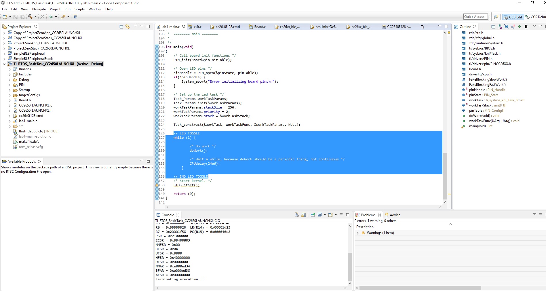
However when I press the resume button on CCS Debug window (so that the pragram that I successfully loaded into my custom board will run and blink the led), the program aborts. I tried the program the CC2650 launchpad before any modification on the board files and the led blinks succesfully. This is the Lab1(BasicTask example) project that I am trying to modify for my custom board ; 

software-dl.ti.com/.../tirtos_01_basic.html

In the RTOS Object Viewer, it seems like the task(which blinks LED) never runs. I am attaching the debug window screenshut below ;

And this is what I get on Console after runnig the progrom on CCS debug window ;

[Cortex_M3_0] {module#38}: line 1087: error {id:0x120000, args:[0x4028, 0x0]}
{module#38}: line 1164: error {id:0x140000, args:[0x2050, 0xe000ed38]}
Exception occurred in background thread at PC = 0x000040e8.
Core 0: Exception occurred in ThreadType_Main.
Main name: main(), handle: 0x0.
Main stack base: 0x20004c00.
Main stack size: 0x400.
R0 = 0x00000000 R8 = 0x00000020
R1 = 0x20004f4c R9 = 0x00000000
R2 = 0x00000001 R10 = 0x00000000
R3 = 0xfffffffd R11 = 0x00000000
R4 = 0x20001f4c R12 = 0x00000000
R5 = 0x00000001 SP(R13) = 0x20004f40
R6 = 0x00000020 LR(R14) = 0x00001d23
R7 = 0x20001f58 PC(R15) = 0x000040e8
PSR = 0x21000000
ICSR = 0x00400803
MMFSR = 0x00
BFSR = 0x04
UFSR = 0x0000
HFSR = 0x40000000
DFSR = 0x00000001
MMAR = 0xe000ed34
BFAR = 0xe000ed38
AFSR = 0x00000000
Terminating execution...

I have checked the supply voltages to the cc2640 on my custom board and they are all ok. I know that there is an  external flash chip on the CC2650 Launchpad board Hence, maybe I should also edit the "cc26x*f128.cmd" file on the lab1 project(BasicTask example). But I am not sure and I do not have much idea about how and why to modify it.

I am struggling to blink the LED on my custom board for days and could not make much progress, please help, any suggestion is deeply appreciated...

Thanks


  • Hi,

    Can you try to move the LED toggle into main.c before bios_start() so that we know that you can actually control the device?
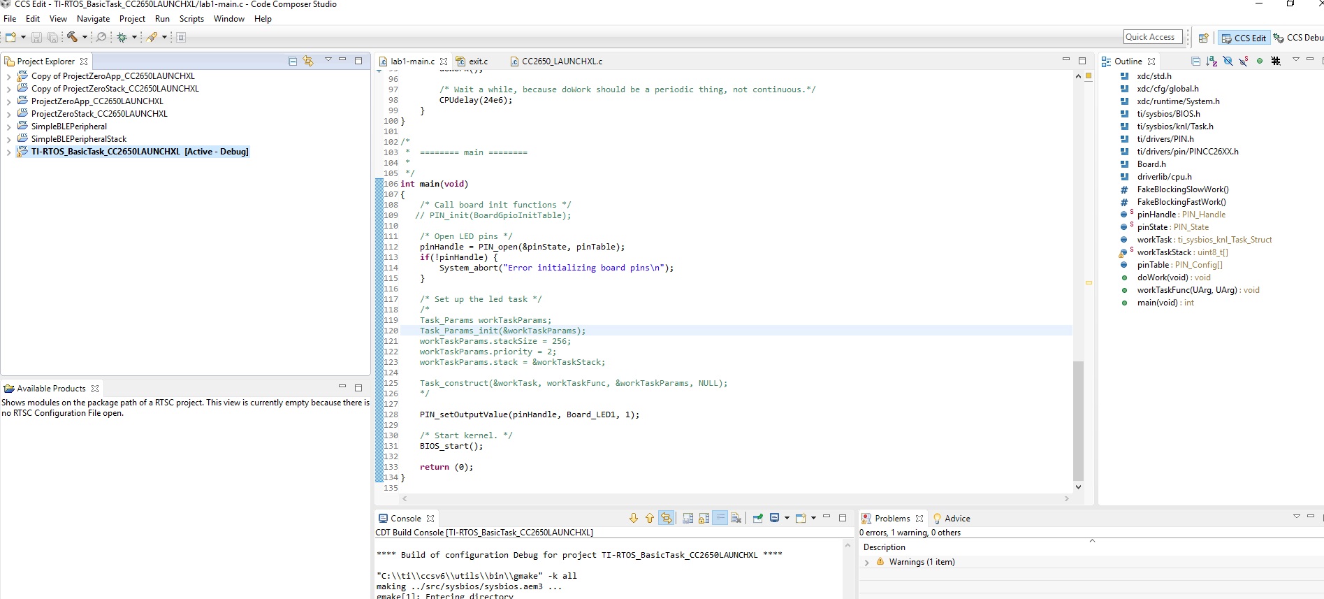
  • I copied the related piece of code  right beforr bios_start() as seen below ;

     And this is what I am getting when I try to run it on the debug window ;

    The led on my custom board does not blink again.

    Can you please let me know what do you mean by "controlling the device".. Does this result mean that the code does not downloaded into the cc2640 ? Please note that I am getting no error while downloading my code into my custom board. It seems to be downlaoded into my board successfully..

    Thank you a lot for your help

  • Hi,

    Can you just use Pin_setOutputValue() in your main.c instead of the while (1), and also commend out the task construct.

    The whole main should have only PIN_open, Pin_setOutputValue and then bios_start.

    After you enter bios_start, can you also check the current on your custom HW to see if the device actually goes into standby mode?
  • Hi,

    I commented out the task construct and only used PIN_open, Pin_setOutputVlue and then bios_start as can be seen below (I also tried without commenting out the "PIN_init(BoardGPIOInıtTable" but there was no change in the results that I summerized below)  ;

    I also want to put my set-up below. My board is supplied by a lipo battery. I connected a multimter between lipo battery and board in order to measure the current flow. In this picture the reading of multimter is shown while the downloading code and it was always changing during the downlaow, I also monitored the current consumption while the custom board is not connected to cjtag.

    There is an RGB led on my custom board. I removed it from my custom board as it is lighting red whenever battery is plugged in. After removing the led, the only component that consumes power is my CC2640 (there is a third chip on the board but the external crystall that it uses is not connected. Surely, it can not run and consume power). I connected a multimeter between my board and the battery to measure the current consumption of CC2640. Multimeter shows 5.7 mA current flow from battery to board. This was suprising to me because I was expecting way less than this. I have checked whether CC2640 making a bluetotoh broadcasting by using my phone's bluetooth, but there was no advertising. Please note that I observed 5.7 mA reading WHILE the cjtag of launchpad is not connected to my custom board.

    After that, I made the cjtag connection between launchpad and my custom board and tried to monitor the current reading when I press the resume button on CCS debug window, but there was no change in the current reading and CCS was again aborting the execution as I send in the previous post.

    Thank you for your help.

  • Hi there,

    Does the LED pin of your custom board correspond to one of the pins on the launchPad? If so, can you use your current settings and run on the LP, then use a DMM to see if the GPIO is toggling?

    This is a way of taking your custom hardware out of hte picture.
  • Hi,

    Thank you for your reply. Yes, the led corresponds to DIO3 on launchpad, I tested the code on launchpad and pin on the launchpad toggles. 

    Does this mean that the problem is not in the code but in my custom hardware ? If so, what might be the problem ? Can you make comments on 5.7 mA current consumption of CC2640 on my custom device(no ble broadcasting).

    Thank you a lot

  • Hi,

    You can post your schematic and layout here so we can have our HW expert to take a look at it.
  • Hi,

    Thank you for your response, In my schematic, VDDS and VDDR are supplied from external LDOs. DC DC converter pins are floating.

    In this schematic, 3.0V supply voltage comes from LDO2 and 1.8V supply voltage comes from LDO1. The SPI pins (on CC2640) runs a third chip which is not visible in the above schematic, it is just a sensor chip and communicates with CC2640 using SPI.

    Is there wrong connection regarding CC2640 ? I think the core of the CC2640 is not working and it might have something to do with the supply voltage configurations..

    Thank you for your help

  • This HW set-up will not work. The VDDR voltage will be supplied from the internal DCDC and/or internal LDO, not and external power supply, unless you are using external regulator mode. If you intend to use external regulator mode, VDDS_DCDC and DCDC_SW should be grounded and the DCDC must be disabled in SW. And further for external regulator mode, the VDDR and VDDS must be tied together and voltage range is 1.7- 1.95 V. See www.ti.com/.../swra498.pdf for more regarding external regulator mode.

    If you plan to use VDDS at 3.0 V (normal mode), then you must use either the internal DCDC or LDO to provide the VDDR voltage. The internal DCDC will require more external components but give you a lower current. If using the LDO, the VDDR pins must be connected together, the VDDS_DCDC must have power and you still need the 10 uF cap in addition to 100 nF decoupling caps on the two VDDR pins. The decoupling caps for the VDDS pins should also be 100 nF (both when using the internal DCDC and LDO). Further, the 24 MHz crystal has an internal cap array providing the correct load. If you are to use external load, this must be disabled in SW, see processors.wiki.ti.com/.../CC26xx_Tips_and_Tricks.

    Have you looked at this wiki processors.wiki.ti.com/.../CC26xx_HW_Troubleshooting
  • Thank you for your information, I am currently editing my hardware according to your suggestions. I want to make clear one more point.

    As I mentioned in the previous posts, I am editing the Lab-1 project that I found in "SimpleLink Academy" which basically toggles an LED on a CC2650 launchpad board. In order to port this particular project(which is developed to run on cc2650 launchpad), I am changing the board.h file in order to match my led pin with the software. I am also changing the configuration settings from cc2650 to cc2640 chip and choosing 2 pin cJtag. Do I have to change any other thing in the software ? Do I need to modify the .cmd file in order to port Lab-1 project to my custom CC2640 board ?
  • Hi there,

    In addition to following Charlotte's suggestions for hardware changes, in order to port the project you should have to :

    1. Change the board file (match up your custom hardware's pins, etc) See section 10.1 of the Software Developer's guide
    2. Change BLE User config (if you are using different RF settings than 7ID EM, else leave as is). The comments in this file provide great guidance on how to edit it
    3. The linker file should not need to be changed
    4. You also shouldn't have to change the device type either, see section 2.5.2.2.2 of the Software Developer's guide
  • Thank you alot for your great help, I am making very good proggress. I worked out all the steps again and I realized that there might be a voltage level issue on my setup.

    As I mentioned before, I am programming my custom hardware with a launchpad(Please look at the picture which shows my setup that I send in the previous posts ). I observed the signal levels on TMS and TCK with a socpe and realized the following;

    I am observing 3V at cc2640 supply pin as expected when cjtag jumper wires are disconnected from my custom board. However, when I connect cjtag to my board, the supply becomes 3,6V. Also, during downloading the program to my custom board, I observed that TMS and TCK voltages are trying to reach 5V. These signals are firstly making a spike at 4V and immedeately drops to 3.6V. I think the clamp diodes on TCK and TMS lines are turning on as the supply voltage seems 3.6V (which indeed should be 3.0V as my LDO normally outputs 3.0V)

    After this, I realized that there is a seperate group of pins of launchpad which is dedicated to be used for external programming.(the pins that are almost at top right corner..) The pins that I was using for programming my board are connected to the CC2650 chip of launchpad, I was peeling off he pin connectors(disconnecting the on-board XDS100 from CC2650 on the launchpad) and putting jumper wires between those pins and my board.

    Might this over voltage issue burn my CC2640 chips as there exised overvoltage on TMS and TCK pins.. As I mentioned my previous posts, I was not able to run my CC2640 board altough I was able to download program.. If they are burned because of exessive voltage, this would be a great explanation for why they are not working...

    Any suggestion/comment is depply appreciated, thank you all..

  • Hi,

    Can anybody help to the issue above ? Whenever I try to program my custom board first time, I think I am burning CC2640. After programming, the output voltage of my LDO jumps from 3.0 V to 3.6 or 4.2 V. When I get rid of CC2640 from the board, the LDO output turns back to 3.0V. I am always replacing(getting rid off the burned one and putting a new one on the board) my cc2640 when the voltage jumps from 3.0V to 3.6 or 4.2 V and the LDO output becomes 3.0V again. What might be the reason of this situation ?

    The voltage on TMS and TCK lines are normally 3.3V. Can this voltage level harm the CC2640 as the LDO that is supplying it(Connected to VDDS) gives 3.0V output normally..

    Any comment is deeply appreciated.

    Thank you all

    Kerem

  • Hi,

    The IOs including JTAG should not operate at the voltage level higher than VDDS, this can potentially damage the chip. Can you post your schematics and layout, we can have our HW expert to take a look at it.
  • Hi,

    Thank you for your help, I accidentally connected battery out(which is 4.2V) to one of the pins, that was why I was seeing 3.7 volts on supply rail. Other than that, the code was still not running but when I have changed the " CPUdelay(24e6) " statement in the code to "Task_sleep(1000) ;" , the code run properly. I still do not now how and why..

    Thank you for your help.
  • You should make sure your HW is operating under normal condition. Any out of spec operation might lead the chip to operate abnormally. You should not try to find a reason why it's working or not when your HW is not following the design/operational spec.
  • Hi, thank you for your help again.

    I think I am misunderstood in my last post. What I meant to say is; the code was still not runnig even though I fixed the hardware(I checked th HWI Troubleshut Guide step by step and everything was ok), it worked  when I have changed the " CPUdelay(24e6) " statement in the code to "Task_sleep(1000) ;"

    In other words, with properly working hardware, "CPUdelay(24e6)" somehow does not work and ends with "loader_exit()" function in exit.c.. and I do not know why..

    I have solved the issue anyway, many many thanks for your great help.

    Kerem