This thread has been locked.

If you have a related question, please click the "Ask a related question" button in the top right corner. The newly created question will be automatically linked to this question.

About default TX power when I enable CC2592 on CC2640.

Other Parts Discussed in Thread: CC2592, CC2640, CC2650, Z-STACK, BLE-STACK

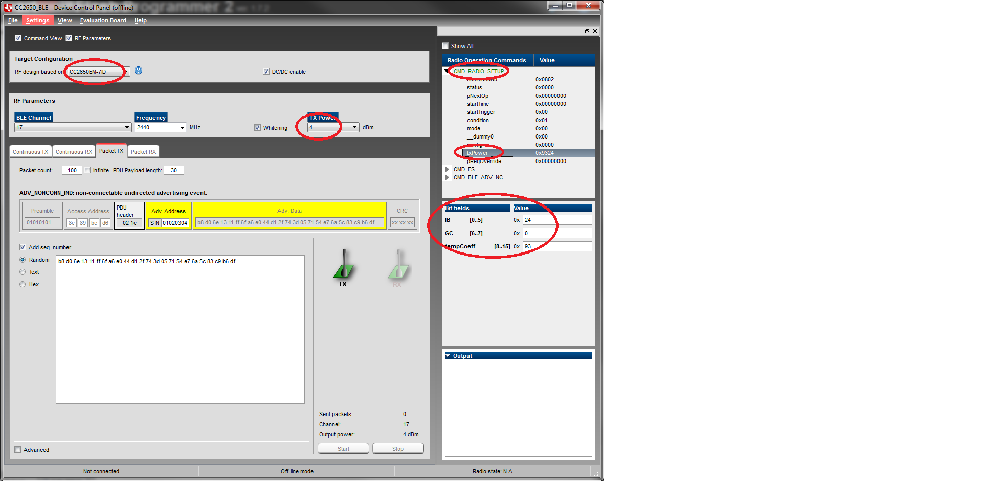
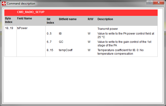
I have followed the solution in to enable CC2592 on CC2640. With those settings, what is the default TX power?

  • Can anyone from TI help on this topic?
  • Hello Yikay,
    You need to refer to the CC2592 data sheet Figure 5. Output Power, PAE, and Current Consumption Versus Input Power. The input power is the same as the CC2650 output power. Default output power on CC2640 with the BLE stack is 0 dBm. I also notified a colleague who might have some more feedback.
  • Hi,
    If you look in this document www.ti.com/.../tidub71.pdf you will find the recommended PA table for the CC26xx and CC2592 (PA setting and expected output power).

    I see that this is not the same PA table that you find in the BLE stack (made for CC26xx stand-alone). If you are looking for the output power for the PA settings found in the BLE stack when you add the CC2592, let me know and I will loop in the team that made the CC26xx-CC2592 board to help you as I unfortunately do not have this HW to measure on.
  • Hi CHS and Eirik,
    Thanks for your help. I know BLE stack v2.1. uses 0 dbm as default TX power when it runs on CC2640. I just need to know what TX power would be when I add CC2592 to HW and SW. Beside, I would also like to know how to change TX power from BLE stack when I use CC2640 with CC2592. Please advise.
  • So following the BLE stach power table for internal bias and differential configuration, the TX power 0x1C is the 3 dBm. According to the CC2650-CC2592 documentation, this equals 20.9 dBm for the CC2650-CC2592 HW. The BLE stack TX power setting for 1 dBm is 0x14 and I expect the output power from the CC2650-CC2592 HW to be close to 0x12 output power so just below 19.5 dBm.

    As I do not have the CC2650-CC2592 HW, I cannot check the output power for the BLE stack 0 dBm setting, , can you please provide the output power from the CC2650-CC2592 HW when using the typical 0 dBm setting?

    The PA tables used in the ble stack are found in the bleUserConfig.c in the CC2640App folder.
  • According to bleUserConfig.c in the CC2640App folder, I see txPowerTable as the followings:

    const txPwrVal_t txPowerTable[] =
      { { TX_POWER_MINUS_21_DBM, GEN_TX_POWER_VAL( 0x07, 3, 0x0C ) },
        { TX_POWER_MINUS_18_DBM, GEN_TX_POWER_VAL( 0x09, 3, 0x0C ) },
        { TX_POWER_MINUS_15_DBM, GEN_TX_POWER_VAL( 0x0B, 3, 0x0C ) },
        { TX_POWER_MINUS_12_DBM, GEN_TX_POWER_VAL( 0x0B, 1, 0x14 ) },
        { TX_POWER_MINUS_9_DBM,  GEN_TX_POWER_VAL( 0x0E, 1, 0x19 ) },
        { TX_POWER_MINUS_6_DBM,  GEN_TX_POWER_VAL( 0x12, 1, 0x1D ) },
        { TX_POWER_MINUS_3_DBM,  GEN_TX_POWER_VAL( 0x18, 1, 0x25 ) },
        { TX_POWER_0_DBM,        GEN_TX_POWER_VAL( 0x21, 1, 0x31 ) },
        { TX_POWER_1_DBM,        GEN_TX_POWER_VAL( 0x14, 0, 0x42 ) },
        { TX_POWER_2_DBM,        GEN_TX_POWER_VAL( 0x18, 0, 0x4E ) },
        { TX_POWER_3_DBM,        GEN_TX_POWER_VAL( 0x1C, 0, 0x5A ) },
        { TX_POWER_4_DBM,        GEN_TX_POWER_VAL( 0x24, 0, 0x93 ) },
        { TX_POWER_5_DBM,        GEN_TX_POWER_VAL( 0x30, 0, 0x93 ) } };

    I also get RF_TX_POWER_TABLE from TI Z-Stack Home 1.2.2a with CC2592 enable as the followings:

    #ifdef PA_LNA_CC2592

        /* CC2592 TX power table is a place holder. Further calibration is required and
         * should not be used without contacting TI support.
         */
        #define RF_FE_MODE_AND_BIAS       ( RF_FE_DIFFERENTIAL | RF_FE_INT_BIAS)
        #define RF_TX_POWER_TABLE         { \
          20,  /* tramsmit power level of the first entry */ \
          (uint16)(int16)0, /* transmit power level of the last entry */ \
          /*  20 dBm */   TX_POUT( 0x30, 0, 0x93 ),  /* characterized as 20 dBm in datasheet */ \
          /*  19 dBm */   TX_POUT( 0x24, 0, 0x93 ),  /* characterized as 20 dBm in datasheet */ \
          /*  18 dBm */   TX_POUT( 0x1C, 0, 0x5A ),  /* characterized as 19 dBm in datasheet */ \
          /*  17 dBm */   TX_POUT( 0x18, 0, 0x4E ),  /* characterized as 19 dBm in datasheet */ \
          /*  16 dBm */   TX_POUT( 0x14, 0, 0x42 ),  /* characterized as 19 dBm in datasheet */ \
          /*  15 dBm */   TX_POUT( 0x21, 1, 0x31 ),  /* characterized as 18 dBm in datasheet */ \
          /*  14 dBm */   TX_POUT( 0x21, 1, 0x31 ),  /* characterized as 18 dBm in datasheet */ \
          /*  13 dBm */   TX_POUT( 0x21, 1, 0x31 ),  /* characterized as 18 dBm in datasheet */ \
          /*  12 dBm */   TX_POUT( 0x18, 1, 0x25 ),  /* characterized as  - dBm in datasheet */ \
          /*  11 dBm */   TX_POUT( 0x18, 1, 0x25 ),  /* characterized as  - dBm in datasheet */ \
          /*  10 dBm */   TX_POUT( 0x18, 1, 0x25 ),  /* characterized as  - dBm in datasheet */ \
          /*  9  dBm */   TX_POUT( 0x12, 1, 0x1D ),  /* characterized as  - dBm in datasheet */ \
          /*  8  dBm */   TX_POUT( 0x12, 1, 0x1D ),  /* characterized as  - dBm in datasheet */ \
          /*  7  dBm */   TX_POUT( 0x12, 1, 0x1D ),  /* characterized as  - dBm in datasheet */ \
          /*  6  dBm */   TX_POUT( 0x0E, 1, 0x19 ),  /* characterized as  - dBm in datasheet */ \
          /*  5  dBm */   TX_POUT( 0x0E, 1, 0x19 ),  /* characterized as  - dBm in datasheet */ \
          /*  4  dBm */   TX_POUT( 0x0E, 1, 0x19 ),  /* characterized as  - dBm in datasheet */ \
          /*  3  dBm */   TX_POUT( 0x0B, 1, 0x14 ),  /* characterized as  - dBm in datasheet */ \
          /*  2  dBm */   TX_POUT( 0x0B, 1, 0x14 ),  /* characterized as  - dBm in datasheet */ \
          /*  1  dBm */   TX_POUT( 0x0B, 1, 0x14 ),  /* characterized as  - dBm in datasheet */ \
          /*  0  dBm */   TX_POUT( 0x0B, 3, 0x0C ),  /* characterized as  0 dBm in datasheet */ \
          /*  Filler */   0,                                                                    \
          /*  Filler */   0,                                                                    \
          /*  Filler */   0,                                                                    \
          /*  Filler */   0,                                                                    \
          /*  Filler */   0,                                                                    \
          /*  Filler */   0                                                                     \
        }

    If you compare two table, I would say CC2640+CC2592 with BLE default TX power, which means CC2640 output 0dbm on TX, the CC2640+CC2592 should get 13~15 dbm. Am I correct? By the way, we can use Z-Stack API Zstackapi_sysSetTxPowerReq to set TX power to 19dbm or other value. Does BLE stack has related API or HC command?

  • In page 3 of www.ti.com/.../tidub71.pdf , it says "The value specified in the table refers to the combined value of txPower.IB and txPower.GC." However, there is no other details about how to combined value of txPower.IB and txPower.GC. Can you also tell me how to do it from BLE Stack source code to map it?
  • If you use SmartRF studio, and press CMD_RADIO_SETUP on the right side of the config window and double-click on tx power, you will get more info on the mapping of gc and ib. 

    You will also find information on the temp coeffsient. 

    So for the stack, the numbers given in the PA tables is given as follows:  Pout, GEN_TX_POWER_VAL(IB, GC, TC). 

    So the table given in the CC2650 CC2592 table translates to: 

    TXPOWER GC IC TC
    0x3F 0 0x3F NA
    0x1C 0 0x1C NA
    0x0E 0 0x0E NA
    0x0B 0 0x0B NA
    0x53 1 0x13 NA
    0x51 1 0x11 NA

    The temp coeff is not given in the table,  can you comment on what value you used for the temp coeff when you made the PA table? 

  • The table given in the stack is not finalized it looks like. As the setting just below 1 dB setting in the BLE stack gives 19.5 dBm, I would estimate that the 0 dBm setting gives more than 15 dBm, again looping in the designers of this board.
  • You provides lots of data but I still cannot get conclusion about what is the final TX power of CC2640-CC2592 when TX power of CC2640 is set to 0 dbm in BLE Stack.
  • I am sorry if I was not clear. The simple answer, I do not know what the output power will be using the default setting in the BLE stack (0 dBm) and unfortunately I do not have any HW so I can measure it for you. That is why I am trying to loop in the team that made the design and that has the HW.
  • OK, let's wait and see if SVS can provide some solid informations.
  • Any update from your or SVS?
  • Hi YiKai,

    I have not measured on the CC2650-CC2592EM myself, but based on what you posted earlier in this thread and experience from other boards with CC2592, I think you should get around 15 dBm output power at the 0 dBm setting and slightly above 20 dBm at the 5 dBm setting.

    Do you have any specific requirements or concerns?

    Cheers,
    Fredrik
  • We need to know exact TX output power for return loss and TRP measurement. Can you confirm CC2640-CC2592 would output 15 dbm at the 0 dBm setting?
  • The only way to know the output power is to perform a conducted measurement on your specific board.
  • We are doing measure on our CC2640-CC2592 design and that's why we need to know expected TX output power to compare with our measured result when BLE stack sets 0 dbm as TX power on CC2640. Why is it so difficult to get expected TX output power of CC2640-CC2592 according to BLE stack setting and data sheet?
  • Hi,
    I am very sorry this is taking so much time! I am looping in the manager for the team that made this design as well to speed up the progress. Note that this team is based in Dallas, so response will be slightly delayed. Again, very sorry for this.
  • Hi Charlotte,
    I appreciate your help and look forward to getting answer from you soon.
  • Hi Charlotte,
    Do you have any update or feedback from Dallas?
  • Unfortunately no. But now I have escalated the case further so hopefully you will get an answer soon. Sorry for any inconvenience.
  • Any update?

  • It looks like the team in Dallas was out of office last week. But the apps manager there is back now, so hopefully he can give you some feedback today (Dallas time).
  • Last time I use CC2630-CC2592, it takes me more than six months to locate the issue. Hopefully, I won't suffer another six or more months to know the answer.
  • YiKai, 

    We will test this tomorrow (Dallas time), I agree the data in the appnote does not align with the values in SmartRF Studio. Unfortunately the person who did the report is on vacation so we need to do a little digging to find you the answer.

    Regards,
    /TA

  • Thank you.

  • When can you provide a solid answer for this? It's not a good way to have technical support like this. Business opportunities are losing.
  • Any update?
  • Any update?
  • Any update? How is it possible for you to find this answer more than 8 days? Is it that difficult?
  • Any update? We are very dispoint that it takes such a long time for TI to get an answer for this. How is it possible that your RD or AE response so slow?
  • Hi YiKai,

    Unfortunately, as I am located in Oslo, I won't be able to go in the lab and do it myself as all HW is in Dallas.

    That being said, I do not understand why you need the power level for the 0 dBm setting. Further back in this discussion, Charlotte has pointed out that the 1 dBm setting for CC26xx without range extender is very close to one of the settings used in CC2650-CC2592EM characterization. Why not use this as your reference point for comparing performance?

    Also, I guess you would want to run the CC2650 at 5 dBm to get maximum power out of the CC2592, right?

    Cheers,
    Fredrik
  • I have CC2650-CC2592EMK but current SmartRF Studio cannot control it. So, I cannot use it to output a specific TX power to compare with our CC2640-CC2592 design. I just need to know the Default TX power of CC2640-CC2592 if we use 0 dbm. In this way, we can do fine tuning to matching and RF performance. So, what is the expected TX power in theory? 13, 14, or 15 dbm when CC2640 outputs 0 dbm?
  • By the way, what's wrong with Dallas HW team? They respond really slow or even no response!?
  • Are you using the BLE stack? Why not just change the power table in the SW?
  • Yes, I am using BLE Stack v2.1.1. I need the TX power in theory so I can estimate the performance of matching and RF performance.
  • Ok, how about this:

    - In the BLE stack, change the output power to one of the values used in the CC2650-CC2592EM app note
    - - This is done in ble_user_config.c
    - Measure on the EM board
    - Measure on your board
    - Compare the results

    Should be easy, right?
  • If it is possible, it will be easier for our RF engineers to use SmartRF Studio to do this.
  • YK,

    We have released an appnote where we disclose the measurements achieved on 6 units across temperature. Have you seen this appnote?

    Regards,
    /TA

  • YK,

    We have put the characterized data for the CC2650+CC2592 EMK on a WIKI, here is the link.

    processors.wiki.ti.com/.../LNA_with_TIMAC

    Regards,
    /TA
  • Hi TA,
    I had read the application note and link but they don't answer my question. If you can find answer from those information, can you point out where it is?
  • Hi TA,
    Any answer of feedback of this topic?
  • YK,

    Here is the power table that correlates the target power to the Register values needed on the CC2650 for power levels from 10-22dBm output power.

    UPDATE : This table is based on old reference design, new table is here.

    /TA

    Expected output power (dBm)

    txPower register value

    21

    0x5A1E

    20

    0X4816

    19

    0X3612

    18

    0X310E

    17

    0X290C

    16

    0X2555

    15

    0X1D53

    14

    0X1751

    13

    0x1613

    12

    0X154E

    11

    0x0CCF

    10

    0X0CCE

    9

    0X0CCD

  • Thanks a lot!
  • Hi all,

    How do I modify PA table in BLE-stack? I can't find it.
  • How do we integrate this power table into BLE Stack v2.1.1?
  • I change the following table:

    #if defined(CC2650EM_7ID) || defined(CC2650EM_5XD) ||  defined(CC2650EM_4XD)

    // Differential Output
    // ALT: Consider basing this direction on type of output (RF_FE_MODE_AND_BIAS)?

    // Tx Power Values (Pout, IB, GC, TC)
    const txPwrVal_t txPowerTable[] =
      { { TX_POWER_MINUS_21_DBM, GEN_TX_POWER_VAL( 0x07, 3, 0x0C ) },
        { TX_POWER_MINUS_18_DBM, GEN_TX_POWER_VAL( 0x09, 3, 0x0C ) },
        { TX_POWER_MINUS_15_DBM, GEN_TX_POWER_VAL( 0x0B, 3, 0x0C ) },
        { TX_POWER_MINUS_12_DBM, GEN_TX_POWER_VAL( 0x0B, 1, 0x14 ) },
        { TX_POWER_MINUS_9_DBM,  GEN_TX_POWER_VAL( 0x0E, 1, 0x19 ) },
        { TX_POWER_MINUS_6_DBM,  GEN_TX_POWER_VAL( 0x12, 1, 0x1D ) },
        { TX_POWER_MINUS_3_DBM,  GEN_TX_POWER_VAL( 0x18, 1, 0x25 ) },
        { TX_POWER_0_DBM,        GEN_TX_POWER_VAL( 0x21, 1, 0x31 ) },
        { TX_POWER_1_DBM,        GEN_TX_POWER_VAL( 0x14, 0, 0x42 ) },
        { TX_POWER_2_DBM,        GEN_TX_POWER_VAL( 0x18, 0, 0x4E ) },
        { TX_POWER_3_DBM,        GEN_TX_POWER_VAL( 0x1C, 0, 0x5A ) },
        { TX_POWER_4_DBM,        GEN_TX_POWER_VAL( 0x24, 0, 0x93 ) },
        { TX_POWER_5_DBM,        GEN_TX_POWER_VAL( 0x30, 0, 0x93 ) } };
    ...

    to

    #if defined(CC2650EM_7ID) || defined(CC2650EM_5XD) ||  defined(CC2650EM_4XD)

    // Differential Output
    // ALT: Consider basing this direction on type of output (RF_FE_MODE_AND_BIAS)?

    // Tx Power Values (Pout, IB, GC, TC)
    const txPwrVal_t txPowerTable[] =
      { { TX_POWER_MINUS_21_DBM, GEN_TX_POWER_VAL( 0x07, 3, 0x0C ) },
        { TX_POWER_MINUS_18_DBM, GEN_TX_POWER_VAL( 0x09, 3, 0x0C ) },
        { TX_POWER_MINUS_15_DBM, GEN_TX_POWER_VAL( 0xCB, 3, 0x0C ) }, //output 10.2 dbm on CC2592
        { TX_POWER_MINUS_12_DBM, GEN_TX_POWER_VAL( 0x4B, 1, 0x14 ) },//output 12.4 dbm on CC2592
        { TX_POWER_MINUS_9_DBM,  GEN_TX_POWER_VAL( 0x4E, 1, 0x19 ) },//output 15.1 dbm on CC2592
        { TX_POWER_MINUS_6_DBM,  GEN_TX_POWER_VAL( 0x52, 1, 0x1D ) },//output 17.5 dbm on CC2592
        { TX_POWER_MINUS_3_DBM,  GEN_TX_POWER_VAL( 0x58, 1, 0x25 ) },//output 19.7 dbm on CC2592
        { TX_POWER_0_DBM,        GEN_TX_POWER_VAL( 0x61, 1, 0x31 ) },//output 21.3 dbm on CC2592
        { TX_POWER_1_DBM,        GEN_TX_POWER_VAL( 0x14, 0, 0x42 ) },//output 21.6 dbm on CC2592
        { TX_POWER_2_DBM,        GEN_TX_POWER_VAL( 0x18, 0, 0x4E ) },//output 22.1 dbm on CC2592
        { TX_POWER_3_DBM,        GEN_TX_POWER_VAL( 0x1C, 0, 0x5A ) },
        { TX_POWER_4_DBM,        GEN_TX_POWER_VAL( 0x24, 0, 0x93 ) },
        { TX_POWER_5_DBM,        GEN_TX_POWER_VAL( 0x30, 0, 0x93 ) } };

    Am I correct?

  • No, it should be like this:

    #if defined(CC2650EM_7ID) || defined(CC2650EM_5XD) || defined(CC2650EM_4XD)

    // Differential Output
    // ALT: Consider basing this direction on type of output (RF_FE_MODE_AND_BIAS)?

    // Tx Power Values (Pout, IB, GC, TC)
    const txPwrVal_t txPowerTable[] =
    { { TX_POWER_MINUS_15_DBM, GEN_TX_POWER_VAL( 0x0B, 3, 0x0C ) }, //output 10.2 dbm on CC2592
    { TX_POWER_MINUS_12_DBM, GEN_TX_POWER_VAL( 0x0B, 1, 0x14 ) }, //output 12.4 dbm on CC2592
    { TX_POWER_MINUS_9_DBM, GEN_TX_POWER_VAL( 0x0E, 1, 0x19 ) },//output 15.1 dbm on CC2592
    { TX_POWER_MINUS_6_DBM, GEN_TX_POWER_VAL( 0x12, 1, 0x1D ) },//output 17.5 dbm on CC2592
    { TX_POWER_MINUS_3_DBM, GEN_TX_POWER_VAL( 0x18, 1, 0x25 ) },//output 19.7 dbm on CC2592
    { TX_POWER_0_DBM, GEN_TX_POWER_VAL( 0x21, 1, 0x31 ) },//output 21.3 dbm on CC2592
    { TX_POWER_1_DBM, GEN_TX_POWER_VAL( 0x14, 0, 0x42 ) },//output 21.6 dbm on CC2592
    { TX_POWER_2_DBM, GEN_TX_POWER_VAL( 0x18, 0, 0x4E ) }}; //output 22.1 dbm on CC2592
  • Can you explain why Temp Coefficient in Hex=14, GC in Hex=1, and Power Setting in Hex=b but Register Value=0x144b when Target Power dBm=12/11 in power table?
  • for the -12 dBm setting that will give you an output power of 12.4 dBm when including the CC2592, the setting is 0x144B.  From that:  

    • Bit [15:8] thus 0x14 is the temp coeff
    Bit [7:0] thus 0x4B is the combined IB and GC. 0x4B is 0b01001011. 
    • Bit [7:6] is GC. So GC is 0b01 = 0x01
    • Bit [5:0] is IB  so IB is 0b001011 = 0x0B